Our AI agents configure established physics simulators, create scenarios and scale execution in the cloud, turning physical questions into simulated experience.
Explore the physical models, scenario comparisons and execution workflows behind our ambition to build the reality stack for Physical AI.
One question. An entire investigation.01 → 03
Impact physicsRecorded investigation
YYouEdited research brief
Model a 100 m rock striking the Moon at 18 km/s. Show the early shock and compare its pressure with an analytic reference.Model a 100 m rock striking the Moon at 18 km/s. Show the early shock and compare its pressure with an analytic reference.Model a 100 m rock striking the Moon at 18 km/s. Show the early shock and compare its pressure with an analytic reference.
Research prompt↑
LLaplaceRecorded result
The first 50 milliseconds.
The early-impact model reaches 385.7 GPa, compared with a 391.4 GPa analytic reference.
Original simulation movie · playback speed is illustrative
The run stops at 0.05 seconds. Final-crater estimates come from a separate scaling law.
Recorded workConfigure CastroRun the impactInspect the shockCheck the pressure
Run FDS vegetation-fire scenarios on four slopes, inspect how the flame and flow change, and check whether the measured spread continues after ignition stops.Run FDS vegetation-fire scenarios on four slopes, inspect how the flame and flow change, and check whether the measured spread continues after ignition stops.Run FDS vegetation-fire scenarios on four slopes, inspect how the flame and flow change, and check whether the measured spread continues after ignition stops.
Research prompt↑
LLaplaceRecorded result
Four slopes. A different flame.
The steeper cases place the flame closer to the fuel. Corrected fields show the change and the settings behind it.
Original simulation movie · playback speed is illustrative
Reference grass with no wind. Steeper cases also change the bed and ignition; spread rates remain unvalidated.
Recorded workConfigure four slopesRun FDSCheck ignition effectsCompare fields
Model HCl adsorption and proton transfer near silica, compare molecular methods, and test how water coverage changes the mechanism.Model HCl adsorption and proton transfer near silica, compare molecular methods, and test how water coverage changes the mechanism.Model HCl adsorption and proton transfer near silica, compare molecular methods, and test how water coverage changes the mechanism.
Research prompt↑
LLaplaceRecorded result
One extra water. Another pathway.
Adding a second water changes the computed proton-transfer cost from 54.61 to 17.73 kJ/mol.
Conceptual sketch · saved cluster results
54.61kJ/mol electronic proton-transfer cost
17.73kJ/mol electronic proton-transfer cost
Small-cluster electronic energies, not measured rates or a converged surface free-energy barrier.
Recorded workBuild the clustersChange the water countCompare energiesCheck the limits
To learn how the physical world behaves, AI needs varied situations with meaningful consequences. Simulation lets us create and examine those situations deliberately.
01
Start with physics
Established simulators represent how physical systems behave under specified assumptions, from materials and flows to fields and impacts.
02
Create the situations
Laplace’s agents configure the models, vary the conditions and coordinate scenario execution in the cloud.
03
Build experience for Physical AI
Our ambition is a reality stack that generates training and evaluation cases for systems learning to understand and act in the physical world.
Physical systems, in motion
Watch the physics come into view.
Original simulations, numerical comparisons and explanatory films reveal physical behaviour across the recorded studies.
An editorial film assembled from recorded work. Playback is not live computation, and each scene retains its model limits.
Explore design choices, generate synthetic observations and compare physical models across very different systems.
Aerospace engineering
Explore a constrained design space.
45.16 million reduced-model candidates leave 44,144 designs to inspect and compare.
Reduced-model screening, not 45 million CFD runs. The mass proxy excludes fixed per-unit overhead and requires higher-fidelity checks before a hardware decision.Inspect the design search
Magnetic geophysics
Create a hidden structure and its signal.
Compare two reconstructions of a synthetic magnetic survey over real terrain.
Synthetic magnetic observations and buried structures over real terrain. Fit ratios are not reconstruction-accuracy percentages.Explore the recovered models
Particle synthesis
Connect reaction conditions to particle behaviour.
Follow a model built from published measurements and examine where its predictions fail to transfer.
The ammonia trend is a conditional recipe hypothesis. Held-out-publication errors of 57–178% show that transfer to a new laboratory remains unreliable.Follow the synthesis study
First measure the energy change. Then let the ocean warm.
The same three CO₂ concentrations answer two different questions: what changes while temperature is fixed, and how a simple ocean responds when it can warm.
1. Select a concentration2. Switch the ocean setting3. Compare the saved results
Explore recorded results · 6 completed model runs
Turn up the CO₂. What changes?
Choose a concentration and an experiment. The display switches between the actual saved results, with the physical assumptions kept visible.
Which question are we asking?
Temperature rise relative to 280 ppm (K)
Dots are the three saved runs. The dashed connector is a visual guide; intermediate concentrations were not simulated here.
Warming vs 280 ppm+1.80 KSlab-ocean equilibrium comparison
Mean model surface temperature17.66 °CYears 9–12 of a 12-year model run
This is an idealized aquaplanet. The slab ocean is 30 m deep; there is no realistic land, sea ice, seasons or ocean circulation. These are conditional model responses, not an Earth climate-sensitivity estimate.
Describe the world. Create the scenarios. Run the physics.
01
Define the experience
Describe the physical system, the range of conditions and what you want to understand or test.
02
Configure the physics
Laplace’s agents prepare established simulators with the models, inputs and assumptions for the question.
03
Generate and run scenarios
The agents create case variations, coordinate execution in the cloud and retain the resulting outputs.
04
Inspect and extend
Examine the numerical results and model limits, then choose which conditions or explanations to explore next.
Follow Laplace’s agents across atmospheric dynamics, impact physics and subsurface inference, from configuring simulators to comparing the worlds they produce.
Models, scenarios and execution across materials, flow, weather and subsurface systems: 13 scientific studies, three engineering notes and one unresolved investigation.
Model HCl adsorption and proton transfer near silica, compare molecular methods, and test how water coverage changes the mechanism.Model HCl adsorption and proton transfer near silica, compare molecular methods, and test how water coverage changes the mechanism.Model HCl adsorption and proton transfer near silica, compare molecular methods, and test how water coverage changes the mechanism.
Research prompt↑
LLaplaceRecorded result
A proton relay changes the energy comparison.
A second water molecule provides a relay route for proton transfer in the small-cluster models. The computed electronic-energy cost falls from 54.61 to 17.73 kJ/mol.
Original study output
The headline compares small-cluster electronic energies, not measured reaction rates or a converged surface free-energy barrier.
Find a low-mass pressurised-air system across the specified flow, altitude, pressure and flight-speed envelope, and show which design choices control the tradeoff.Find a low-mass pressurised-air system across the specified flow, altitude, pressure and flight-speed envelope, and show which design choices control the tradeoff.Find a low-mass pressurised-air system across the specified flow, altitude, pressure and flight-speed envelope, and show which design choices control the tradeoff.
Research prompt↑
LLaplaceRecorded result
65.8% lower minimum mass proxy.
Allowing stage loading to vary lowers the minimum mass proxy from 1,505.5 to 515.2 kg within the reduced model. Both the fixed-loading and variable-loading searches contain feasible designs.
Original study output
These are reduced-model candidates and a mass proxy, not individual CFD runs or manufactured weight savings.
Use CESM to compare higher CO₂ levels, first holding ocean temperature fixed and then letting a simple ocean warm, so the energy change and temperature response can be separated.Use CESM to compare higher CO₂ levels, first holding ocean temperature fixed and then letting a simple ocean warm, so the energy change and temperature response can be separated.Use CESM to compare higher CO₂ levels, first holding ocean temperature fixed and then letting a simple ocean warm, so the energy change and temperature response can be separated.
Research prompt↑
LLaplaceRecorded result
Three CO₂ levels. Two ocean setups. Six experiments.
The fixed-temperature runs isolate an energy response, while the 30 m slab-ocean runs allow warming. The approximate 1.87 K response per CO₂ doubling belongs to this idealized aquaplanet.
Original study output
The aquaplanet has a 30 m slab ocean and lacks realistic land, sea ice, seasons and ocean circulation.
Run FDS vegetation-fire scenarios on four slopes, inspect how the flame and flow change, and check whether the measured spread continues after ignition stops.Run FDS vegetation-fire scenarios on four slopes, inspect how the flame and flow change, and check whether the measured spread continues after ignition stops.Run FDS vegetation-fire scenarios on four slopes, inspect how the flame and flow change, and check whether the measured spread continues after ignition stops.
Research prompt↑
LLaplaceRecorded result
Four slopes reveal a change in flame shape.
The recorded FDS scenarios show the flame lying closer to the fuel in the steeper cases. Corrected temperature fields, flow fields and two movies make that change visible alongside the scenario settings.
Original study output
The cases use reference grass, no ambient wind and one grid resolution.
Using real terrain and synthetic magnetic observations, compare smooth and compact reconstructions to see whether different underground structures can fit the same survey.Using real terrain and synthetic magnetic observations, compare smooth and compact reconstructions to see whether different underground structures can fit the same survey.Using real terrain and synthetic magnetic observations, compare smooth and compact reconstructions to see whether different underground structures can fit the same survey.
Research prompt↑
LLaplaceRecorded result
108,484 cells. Two plausible reconstructions.
Smooth and compact inversions both fit the synthetic magnetic signal while placing susceptibility differently underground. Their disagreement makes the need for another constraint visible.
Original study output
The terrain is real, but the buried structures and magnetic observations are synthetic.
Estimate the water contact angle of coated silica from its chemistry, then test whether surface texture could explain the higher measured angle.Estimate the water contact angle of coated silica from its chemistry, then test whether surface texture could explain the higher measured angle.Estimate the water contact angle of coated silica from its chemistry, then test whether surface texture could explain the higher measured angle.
Research prompt↑
LLaplaceRecorded result
A mismatch becomes a specific experiment.
The model gives a 115.3° intrinsic contact angle, while a suspended drop on the considered sphere packings gives 125–129°. The 130° measurement was disclosed before the texture explanation was developed.
Original study output
The texture explanation assumes water is suspended on sphere tops; that wetting state has not been observed.
Model silica-particle synthesis from published recipes, identify conditions worth testing for particles above 100 nm, and check whether the model transfers between studies.Model silica-particle synthesis from published recipes, identify conditions worth testing for particles above 100 nm, and check whether the model transfers between studies.Model silica-particle synthesis from published recipes, identify conditions worth testing for particles above 100 nm, and check whether the model transfers between studies.
Research prompt↑
LLaplaceRecorded result
Five publications expose the transfer gap.
A model fitted to 207 of 209 assembled observations has about 40% median fitting error. Errors rise to 57–178% when a publication is held out, making local validation the next step.
Original study output
The crossover near 0.30 M ammonia applies to one fitted scenario and is not a validated production recipe.
Set up Castro experiments, then model the early impact of a 100 m rock striking the Moon at 18 km/s and compare the shock with an analytic reference.Set up Castro experiments, then model the early impact of a 100 m rock striking the Moon at 18 km/s and compare the shock with an analytic reference.Set up Castro experiments, then model the early impact of a 100 m rock striking the Moon at 18 km/s and compare the shock with an analytic reference.
Research prompt↑
LLaplaceRecorded result
The first 50 milliseconds, with a pressure check.
The early-impact calculation reaches a peak pressure of 385.7 GPa against a 391.4 GPa analytic reference. It stops at 0.05 seconds; a final-crater estimate comes from a separate scaling law.
Original study output
The impact run covers only the early 0.05 seconds and does not simulate the final crater.
Run a small CESM atmosphere, extend it to reveal the growth of a disturbance, and explain the evolving weather with diagnostics and a film.Run a small CESM atmosphere, extend it to reveal the growth of a disturbance, and explain the evolving weather with diagnostics and a film.Run a small CESM atmosphere, extend it to reveal the growth of a disturbance, and explain the evolving weather with diagnostics and a film.
Research prompt↑
LLaplaceRecorded result
Ten days of growth, with the numbers behind the film.
Pressure-wave amplitude grows from 0.2323 to 49.7354 hPa between model days one and ten. The diagnostic tables connect that growth to ascent, cloud water and rainfall in the idealized atmosphere.
Original study output
This is idealized atmospheric dynamics, not a forecast or an observational validation.
Run a simple month-long CESM experiment that reveals interesting atmospheric physics with little spinup, then explain its evolution.Run a simple month-long CESM experiment that reveals interesting atmospheric physics with little spinup, then explain its evolution.Run a simple month-long CESM experiment that reveals interesting atmospheric physics with little spinup, then explain its evolution.
Research prompt↑
LLaplaceRecorded result
31 model days. 249 diagnostic samples.
A three-hourly record follows the atmosphere from model day zero through day 31. The saved time series, jet table, charts and film let the evolution be inspected beyond a single viewing.
Original study output
The experiment omits radiation, an evolving ocean and surface friction, so it is not a climate equilibrium or forecast.
Run a sample WRF storm, then build a simpler physical explanation and compare it with the detailed model.Run a sample WRF storm, then build a simpler physical explanation and compare it with the detailed model.Run a sample WRF storm, then build a simpler physical explanation and compare it with the detailed model.
Research prompt↑
LLaplaceRecorded result
One detailed storm. One simpler physical model.
The reduced model produces a 39.8 m/s peak updraft against 44.9 m/s in the mature WRF profile. Other storm properties disagree substantially, exposing which parts of the explanation still need work.
Original study output
This is an idealized model-to-model comparison without observational validation.
Model how cohesive silica powder forms clumps, explore a possible gas-flow operating range, and test what a particle simulation can establish about vibration.Model how cohesive silica powder forms clumps, explore a possible gas-flow operating range, and test what a particle simulation can establish about vibration.Model how cohesive silica powder forms clumps, explore a possible gas-flow operating range, and test what a particle simulation can establish about vibration.
Research prompt↑
LLaplaceRecorded result
Clump size sets the operating hypothesis.
With clump diameter calibrated to 250 µm, the algebraic model estimates fluidization onset near 53.7 mm/s. A separate gas-free particle study shows lower contact counts under vibration, but its control bed was still settling.
Original study output
The particle runs contain no gas, and the 250 µm clump size is a calibration target.
Build a three-dimensional gravity inversion, compare the recovered structure with a known target, and test what a good fit does and does not recover.Build a three-dimensional gravity inversion, compare the recovered structure with a known target, and test what a good fit does and does not recover.Build a three-dimensional gravity inversion, compare the recovered structure with a known target, and test what a good fit does and does not recover.
Research prompt↑
LLaplaceRecorded result
Mass comes close. Absolute depth remains unresolved.
After real-data access failed, a 529-station synthetic study recovered mass 5.02% above the constructed truth. A near-target data-misfit ratio of 1.012 still left the bed-depth geometry unresolved.
Original study output
The observations and target geometry are synthetic, so their recovery errors do not establish field performance.
Run a minimal one-day CESM infrastructure test with dead components, checking case creation, compilation, submission, time-stepping and output recovery.Run a minimal one-day CESM infrastructure test with dead components, checking case creation, compilation, submission, time-stepping and output recovery.Run a minimal one-day CESM infrastructure test with dead components, checking case creation, compilation, submission, time-stepping and output recovery.
Research prompt↑
LLaplaceRecorded result
One completed build-to-output check.
A CESM test with dead model components advances one model day through 48 coupler steps and records restart output. The supplied report provides the acceptance record.
▤cesm_smoke_test_report.mdSaved
The test uses dead components and establishes no climate finding.
Create a Manim visualization specialist and test that its environment can render a short scene for explaining scientific results.Create a Manim visualization specialist and test that its environment can render a short scene for explaining scientific results.Create a Manim visualization specialist and test that its environment can render a short scene for explaining scientific results.
Research prompt↑
LLaplaceRecorded result
An animation toolchain passes its first render test.
A configured Manim environment produces a short test movie and retains its scene source. The result verifies a recorded render path.
▤Manim scene sourceSaved
▤Rendered test movieSaved
This is a rendering setup check with no physical simulation or scientific finding.
Compare available compute environments for CPU and high-performance scientific workloads, and identify what would need to be measured before choosing between them.Compare available compute environments for CPU and high-performance scientific workloads, and identify what would need to be measured before choosing between them.Compare available compute environments for CPU and high-performance scientific workloads, and identify what would need to be measured before choosing between them.
Research prompt↑
LLaplaceRecorded result
A resource comparison leaves a benchmark to run.
The historical discussion compares elastic compute resources with the existing scientific cluster. It provides workload questions, without a simulation or matched performance benchmark.
▤Conversation and source referencesSaved
No simulation or matched benchmark was executed in this session.
Model a supersonic gas eductor in OpenFOAM, diagnose solver failure, and check convergence and mass balance before accepting an entrainment ratio.Model a supersonic gas eductor in OpenFOAM, diagnose solver failure, and check convergence and mass balance before accepting an entrainment ratio.Model a supersonic gas eductor in OpenFOAM, diagnose solver failure, and check convergence and mass balance before accepting an entrainment ratio.
Research prompt↑
LLaplaceRecorded result
A coarse test weakens the mesh-only diagnosis.
A 51,300-cell case also fails, challenging the explanation that fine-grid geometry alone caused the problem. The later run still has unacceptable residuals and roughly 50% mass imbalance, so no entrainment ratio is accepted.
Original study output
The CFD investigation remains unresolved and has no accepted entrainment result.
Follow Laplace’s agents across atmospheric dynamics, impact physics and subsurface inference, from configuring simulators to comparing the worlds they produce.
Describe the world. Create the scenarios. Run the physics.
Start with a physical system and what you want to vary. Laplace’s agents turn that intent into configurations, executions and outputs you can examine.
A check that changed the investigation
Check what actually ran.
In the fire study, launch commands returned successfully while FDS reported only one process. Checking the solver output exposed the mismatch before a successful command could be mistaken for the intended parallel run.
We’re building a reality stack that turns established physics into scenarios for training and evaluating Physical AI.
Laplace’s agents connect scenario design, simulator configuration, cloud execution and numerical outputs. The product starts with the physical system and the conditions you want to explore, then carries the work needed to create and inspect those situations.
Physics as the starting point.
Configure established models with explicit assumptions, material properties and boundary conditions.
Scenarios as the unit of experience.
Vary the conditions, compare the resulting behaviour and identify which situations need further exploration.
Cloud execution inside the workflow.
Bring solver setup, job execution and analysis together in a workflow designed to scale across cloud compute.
Close the loop from simulation to learning.
The next proof is a Physical AI workflow that uses generated cases for training or evaluation, with held-out performance, generation throughput, compute cost and human interventions measured.
The recorded studies demonstrate solver configuration, scenario comparisons, numerical outputs and parallel CPU execution. They do not yet establish a dataset used to train Physical AI, improved learned behaviour or measured elastic-cloud throughput.
Estimate the water contact angle of coated silica from its chemistry, then test whether surface texture could explain the higher measured angle.Estimate the water contact angle of coated silica from its chemistry, then test whether surface texture could explain the higher measured angle.Estimate the water contact angle of coated silica from its chemistry, then test whether surface texture could explain the higher measured angle.
Research prompt↑
LLaplaceRecorded result
A mismatch becomes a specific experiment.
The model gives a 115.3° intrinsic contact angle, while a suspended drop on the considered sphere packings gives 125–129°. The 130° measurement was disclosed before the texture explanation was developed.
The texture explanation assumes water is suspended on sphere tops; that wetting state has not been observed. The intrinsic angle is sensitive to contact separation, and agreement with the disclosed measurement is not independent predictive validation.
An edited brief introduces the recorded investigation. Read the source prompt below for its original context and later steering.
Read the research prompt
Original research prompt
assume silica coated with TMMS, estimate its contact angle with water from first prinicipple (without quoting observation); start with analytical model
One calculation connects molecular packing to a visible surface property, then tests how the result changes with coverage.
Analytical calculations and sensitivity tests. The observed contact angle was known before the texture explanation was proposed.
The work behind the result
Follow the investigation.
Combine coating geometry, water accessibility and interfacial forces to calculate an intrinsic contact angle.
Vary residual sites, surface coverage and contact separation to expose the calculation’s sensitivity.
Use the subsequently supplied 130° measurement to ask whether the sample’s geometry changes the apparent angle.
Calculate the conditional 125–129° range for a suspended drop on the considered sphere arrangements.
Propose hysteresis and packing measurements that can test the texture explanation.
Condensed from the recorded investigation, including later steering and review. Playback does not represent elapsed time.
Inspect the result evidence and download the outputs
Computed baseline: 115.3° intrinsic contact angle under the model’s baseline assumptions. Evidence
Explanation to test: 125–129° for the considered sphere packings, assuming a suspended drop. Evidence summary
Usable handoff: Original calculation code, result files and a proposed hysteresis/packing test. Evidence
The measured 130° was disclosed before the texture explanation was developed. The wetting state remains unconfirmed, and the intrinsic angle has substantial parameter uncertainty.
The produced figure: chemistry, sensitivity and sphere packing. Saved output from this investigation; no new calculation runs in this page.
Model and method
Yes, this includes simulation. Laplace numerically builds and packs molecular groups on a model surface, tests water access, and combines those results with an interfacial-energy calculation. The configurations are static; this is not an atom-by-atom molecular-dynamics trajectory.
How the investigation developed.
An engineer wants to know how water should wet silica coated with trimethylsilyl groups. A contact angle describes how much a drop beads up: a larger angle means less spreading. A single answer matters less than knowing which physical lever controls it. Should the team change the coating chemistry, remove more hydroxyl groups, or change how the particles are deposited?
01
Start from chemistry rather than fitting the angle
The initial request was to estimate the angle from first principles, starting analytically. Laplace assembled a dispersion-force model, built a geometric coating, and estimated which leftover hydroxyl groups a water molecule could reach. The early report gave about 116°; the final refined baseline is 115.3°. It used known material properties and an empirical contact-separation parameter, without using an input contact-angle measurement. The exact final baseline should not be read as a timestamped prediction made before every later revision.
02
Find the mechanism hidden by a surface-chemistry count
The model leaves about 39% of hydroxyl sites unreacted because the coating groups physically crowd one another. What matters is accessibility: the coating shelters the remaining sites. In the model, making those sites accessible would lower the angle to 87.8°. That gives the team a concrete hypothesis: changing the chemical count alone may miss what water actually encounters.
03
Use a discrepancy to change the question
The user then disclosed a measured angle of 130°. Laplace examined a textured bed of silica spheres rather than forcing the smooth-surface model to fit. Assuming water is suspended on the sphere tops, the model gives 125.1–129.2° across the considered packings. The useful output is an explanation to test: particle packing and trapped air may account for the difference between the chemistry and the measurement.
The chemistry-to-texture explanationOriginal result
Original final-session figure. Left: the adhesion budget. Middle: the contact-separation sensitivity. Right: packing changes the apparent angle. Read the 125–129° range as conditional on the suspended-drop model, and alongside the report's wider intrinsic-angle uncertainty. reconciliation.png · Evidence summary
The next test
Measure advancing and receding contact angles and inspect the particle packing before choosing a change in coating chemistry.
Scientific assumptions and limitations
The assumed contact separation is a major uncertainty: the report gives a 98.6–125.9° intrinsic-angle range over its wider parameter interval. The baseline 115.3° is not a high-precision accuracy claim.
The 130° measurement was disclosed before the textured-surface explanation was developed. Agreement is post-disclosure consistency, not independent predictive validation.
The suspended wetting state and sample packing were not directly observed. Static geometry omits thermal motion and does not predict hysteresis.
The same questionWhy does coated silica bead water, and why does the sample read 130°?
Direct the investigation. Inspect the work.
Laplace carries technical execution while researchers set the question, steer the study, and evaluate the evidence.
A team-managed workflowIllustrative workflow with existing tools
Task 1Define the surface
→
Task 2Build the physical model
→
Task 3Implement and run
→
Task 4Check the discrepancy
→
Task 5Assemble the handoff
The team coordinates tools, context, and revisions across the study.
With LaplaceTechnical work demonstrated in these studies
HUMANBrief + steer
Laplace carries the technical work
Frame chemistry and packingConnect physics in codeRun scenariosChallenge the explanationDeliver an inspectable study
↺ Run → inspect → revise, with researcher steering
HUMANReview + decide
Task execution delegatedModel setup, code and output processing are carried inside the recorded investigation.
Revisions stay connectedChanges to the brief and diagnostic corrections share a working record.
Results arrive togetherInspect the files, findings and next test in one handoff.
Illustrates work ownership. Box widths are schematic; human time saved was not measured.
Inspect the work inside the Laplace block
Frame chemistry and packing. Build the molecular layer and its water-accessibility test.
Connect physics in code. Combine dispersion, hydrogen bonding and a wetting relation.
Run scenarios. Explore residual sites, calcination, corrugation and sphere packing.
Challenge the explanation. Investigate the disclosed 130° angle; check sensitivities and claims.
Deliver an inspectable study. Save code, numeric results, figures and a falsifiable mechanism.
↺Both routes need iteration when the model and measurement disagree.
The same physical tasks are connected inside a model–run–review workflow. The useful gain to test is less manual assembly and a faster route to the next experiment.
What this study gathered.
Evidence gathered
A reusable physics calculation
Original code, results JSON, adhesion checks and the final report.
A conventional investigation would connect several pieces of work: surface chemistry and coverage assumptions, a model of how coating molecules fit, interfacial-force calculations, a wetting model, and a comparison with the actual sample. An empirical fit could match an observed angle while hiding the mechanism. A detailed molecular-dynamics study would instead require an appropriate force model and its own sampling and validation effort. Neither route's human effort or total elapsed time was measured in this session.
How to read the timing
These investigations often continued across separate visits. The first and last messages do not measure continuous work.
4d 22h 40m 15sCalendar span of the conversation
50mCombined child-agent windows, with overlapping intervals counted once
Agent windows can include waiting and omit work in the main conversation. They are not a measure of active human work, total compute or time saved. The exports do not provide a reliable labour clock.
Model HCl adsorption and proton transfer near silica, compare molecular methods, and test how water coverage changes the mechanism.Model HCl adsorption and proton transfer near silica, compare molecular methods, and test how water coverage changes the mechanism.Model HCl adsorption and proton transfer near silica, compare molecular methods, and test how water coverage changes the mechanism.
Research prompt↑
LLaplaceRecorded result
A proton relay changes the energy comparison.
A second water molecule provides a relay route for proton transfer in the small-cluster models. The computed electronic-energy cost falls from 54.61 to 17.73 kJ/mol.
The headline compares small-cluster electronic energies, not measured reaction rates or a converged surface free-energy barrier. The periodic calculations were convergence probes; no completed periodic adsorption-energy result or production periodic molecular-dynamics campaign is established.
An edited brief introduces the recorded investigation. Read the source prompt below for its original context and later steering.
Read the research prompt
Selected research prompt excerpt
Develop a simple, validated computational workflow for studying HCl adsorption on generic amorphous silica: first construct several realistic hydroxylated silica surface models with different silanol arrangements and water coverages;
Change the molecular assumption and see the recorded energy comparison.
54.61kJ/mol electronic proton-transfer cost
Start with the one-water cluster. This establishes the comparison for the added-water calculation.
17.73kJ/mol electronic proton-transfer cost
The second water supports a relay pathway. The next question is whether it survives a periodic-surface calculation.
One water 54.61→Two waters 17.73kJ/mol
Scale of the work
periodic CP2K single-point calculations
52
MPI-rank streams per node
4 × 48
reported convergence-batch wall time
~60 min
Four calculations at a time turn a numerical-settings question into a 52-point convergence study.
About 60 minutes for one later CP2K convergence batch, reported across two jobs. This does not time the entire chemistry study or its separate molecular-dynamics demonstration.
The work behind the result
Follow the investigation.
Prepare surface and cluster structures representing different sites and hydration conditions.
Compare seven density-functional methods and retain the energy results for inspection.
Separate ordinary solvation from a proton relay, alongside a bounded 120 ps small-cluster sampling demonstration.
Run 52 convergence checks on unrelaxed geometries and identify the proposed cutoff’s failed force criterion.
Repair defective surfaces, rebuild the hydroxyl-density ladder and specify the periodic calculations still needed.
Condensed from the recorded investigation, including later steering and review. Playback does not represent elapsed time.
Inspect the result evidence and download the outputs
Computed mechanism change: One versus two waters changed the cluster electronic proton-transfer cost from 54.61 to 17.73 kJ/mol. Evidence
Executed demonstration: 120 ps of sampling on a 14-atom GFN2-xTB cluster, with numerical diagnostics. Evidence summary
Usable handoff: Quantum benchmarks, method comparisons, inputs, sampling diagnostics and next research steps. Evidence summary
No periodic adsorption-energy result or production periodic molecular dynamics was completed. The nitric-acid extension produced a pipeline and structures, not composite nitric-acid energetics.
54.61 → 17.73Computed proton-transfer cost, kJ/molOne-water versus two-water cluster electronic energies. These are not measured reaction rates or a periodic free-energy barrier.Evidence summary
120 psDemonstration samplingSix 20-ps walkers on a 14-atom GFN2-xTB cluster; simulated physical time, not elapsed runtime.Evidence summary
The produced figure: how the water-assisted pathway changes method error. Saved output from this investigation; no new calculation runs in this page.
Model and method
Yes. This session contains actual quantum-chemistry calculations and 120 ps of enhanced-sampling molecular dynamics on a small cluster using GFN2-xTB. It also contains periodic CP2K convergence probes. A completed periodic adsorption study or production ab-initio molecular-dynamics campaign is not established.
How the investigation developed.
How does hydrogen chloride land on, react with, and leave a silica surface? The answer changes with the surface's hydroxyl sites and its water coverage. An R&D team needs to know which assumptions dominate the result and which measurement would reduce uncertainty, rather than receiving a single rate for an unspecified surface.
01
Make the workflow executable
Laplace built a connected workflow with surface models, quantum benchmarks, a comparison of seven density-functional methods, simulation inputs, enhanced sampling, and a kinetics module. On initially limited hardware, it ran what was tractable and specified larger calculations separately. The 120-ps dynamics demonstration checked the sampling machinery on a small cluster; it did not simulate an extended silica surface at production fidelity.
02
Extend the calculation where the assumption matters
After cluster access became available, Laplace added missing molecular models and tested numerical settings. The important scientific result came from a second water molecule: the computed proton-transfer cost fell from 54.61 to 17.73 kJ/mol. A controlled comparison separated ordinary solvation from a proton-relay pathway. Water was participating in the mechanism, rather than merely changing the environment.
03
Let better evidence overturn the earlier story
The extension exposed limits in the first-stage picture. A functional-error correction changed on the relay geometry. The proposed plane-wave cutoff failed the project's force criterion. Repairing defective surface structures collapsed the intended hydroxyl-density ladder, prompting a different construction method. The output therefore includes revised models and an explicit account of which earlier claims no longer survive.
The pathway changes the method's errorOriginal result
Original session figure. The comparison distinguishes adding water from enabling a proton relay. It shows why one blanket computational correction can fail on a different reaction geometry. functional_error_1w_vs_2w.png · Evidence summary
A real simulation, with a defined level of fidelityOriginal result
Original demonstration output: free-energy surfaces and sampling diagnostics for the small GFN2-xTB cluster. The apparent agreement with a higher-level energy is explicitly called coincidental in the report. Desorption was not converged; this is not a quantitative prediction for the periodic surface. fes_demo.png · Evidence summary
Detect a broken model set, then rebuild itOriginal result
Original session figure. Repairing defects changed the hydroxyl density; an alternative construction recovered a usable ladder over a narrower range. The lowest originally intended densities remain unrepresented. ladder_rebuilt.png · Evidence summary
The next test
Relax the rebuilt periodic surfaces and calculate adsorption energies, then compare with measurements of water coverage and surface sites.
Scientific assumptions and limitations
The headline 54.61→17.73 kJ/mol compares cluster electronic-energy costs. It should not be described as a measured acceleration or a converged periodic free-energy barrier.
The 52 periodic calculations were numerical convergence probes on unrelaxed geometries. No periodic adsorption energy or full periodic ab-initio dynamics result was produced.
The updated hydration curve and topology-dependent error were not propagated through the full original uncertainty calculation. Experimental comparison remains prospective.
The HNO3 extension delivered a generalised pipeline and structures, but no composite HNO3 energetics. Some first-stage limitation prose remains stale; the later methods, second-stage results and numeric files determine this case study's scope.
The same questionWhich surface and water assumptions control HCl reaction predictions?
Direct the investigation. Inspect the work.
Laplace carries technical execution while researchers set the question, steer the study, and evaluate the evidence.
A team-managed workflowIllustrative workflow with existing tools
Task 1Build surface and cluster models
→
Task 2Choose and benchmark methods
→
Task 3Prepare compute and sampling
→
Task 4Connect chemistry to rates
→
Task 5Review and plan validation
The team coordinates tools, context, and revisions across the study.
With LaplaceTechnical work demonstrated in these studies
HUMANBrief + steer
Laplace carries the technical work
Generate the model setRun quantum benchmarksExecute at stated fidelityRevise the mechanismPackage the next research step
↺ Run → inspect → revise, with researcher steering
HUMANReview + decide
Task execution delegatedModel setup, code and output processing are carried inside the recorded investigation.
Revisions stay connectedChanges to the brief and diagnostic corrections share a working record.
Results arrive togetherInspect the files, findings and next test in one handoff.
Illustrates work ownership. Box widths are schematic; human time saved was not measured.
Inspect the work inside the Laplace block
Generate the model set. Construct surface/cluster assets and record their assumptions.
Run quantum benchmarks. Compare seven functionals and extend to the second-water models.
Execute at stated fidelity. Run 120 ps of cluster sampling and periodic convergence probes.
Revise the mechanism. Separate solvation from proton relay; identify failed numerical criteria.
Package the next research step. Deliver artifacts, corrected scope and a periodic/experimental plan.
↺Review sends the investigation back to the surface, method or pathway that controls the result.
A connected investigation carries models, calculations and revisions across specialist tools. More useful scientific coverage is demonstrated; a labour saving is still to be measured.
What this study gathered.
Evidence gathered
Benchmarks + simulation diagnostics
Quantum-energy files, seven-functional comparisons and demonstration sampling.
A conventional route would build surface structures, choose an electronic-structure method, benchmark it on tractable molecules, prepare periodic calculations, run sampling, translate energies into kinetics, and compare with experiments. This crosses quantum chemistry, molecular simulation, cluster computing and kinetic modelling. The session's own production-runtime estimates are assumptions for a proposed periodic calculation, not a measured conventional-project baseline.
How to read the timing
These investigations often continued across separate visits. The first and last messages do not measure continuous work.
5d 11h 47m 18sCalendar span of the conversation
21h 07mCombined child-agent windows, with overlapping intervals counted once
Agent windows can include waiting and omit work in the main conversation. They are not a measure of active human work, total compute or time saved. The exports do not provide a reliable labour clock.
A fixed assumption hides a lighter part of the design space.
The question. The result.
Aerospace engineeringRecorded investigation
YYouEdited research brief
Find a low-mass pressurised-air system across the specified flow, altitude, pressure and flight-speed envelope, and show which design choices control the tradeoff.Find a low-mass pressurised-air system across the specified flow, altitude, pressure and flight-speed envelope, and show which design choices control the tradeoff.Find a low-mass pressurised-air system across the specified flow, altitude, pressure and flight-speed envelope, and show which design choices control the tradeoff.
Research prompt↑
LLaplaceRecorded result
65.8% lower minimum mass proxy.
Allowing stage loading to vary lowers the minimum mass proxy from 1,505.5 to 515.2 kg within the reduced model. Both the fixed-loading and variable-loading searches contain feasible designs.
These are reduced-model candidates and a mass proxy, not individual CFD runs or manufactured weight savings. Fixed overhead is excluded, the lightest point has only about 0.20% margin on its tightest modelled constraint, and no conservation-verified CFD loss result was obtained.
An edited brief introduces the recorded investigation. Read the source prompt below for its original context and later steering.
Read the research prompt
Original research prompt
the design space is (1) total air flow 2ton/hr to 10ton/hr (2) altitude 50,000feet to 60,000feet (3)2bar to 4 bar (4)mach 0.7 to 0.9; optimizioan should be on total mass and/or fuel; no need to cool the pressurzied air generated; add some 3D visualziation, the report should read as an optimization report that generate and explain what is the best system
Modelled tradeoff: 515.2 kg minimum mass proxy versus 1,505.5 kg with stage loading frozen: 65.8% lower within the model. Evidence
Correction retained: The frozen-loading search still has 20 feasible designs. The earlier infeasibility explanation was withdrawn. Evidence
These are reduced-model search results and a mass proxy. The initial CFD trial did not yield a conservation-verified loss prediction, and the geometry images are not completed 3D CFD.
45.16 millionCandidate grid points screenedNot 45 million CFD runs. Diffusion screening and early rejection avoid evaluating every corner for every candidate.Source
44,144Grid designs admitted by the modelSurvivors pass constraints at all eight evaluated mission-box corners; count depends on grid resolution.Source
65.8%Lower minimum modelled mass515.2 versus 1,505.5 kg in expanded versus frozen-loading searches. This is a model comparison, not a built-system saving.Source
The produced figure: feasible designs and the constraints that bind. Saved output from this investigation; no new calculation runs in this page.
Model and method
Yes, in the broad engineering sense. The final result evaluates a thermodynamic and mean-line model across many candidate systems. An initial SU2 cascade trial was run but did not produce a conservation-verified loss prediction. The 3D figures visualise geometry; they are not results of a completed 3D flow simulation.
How the investigation developed.
The user initially asked for an open-source 2D CFD program for compressor and turbine blades. The task evolved into designing a hot pressurised-air supply: 2–10 tonnes per hour, 2–4 bar absolute, at 50,000–60,000 feet and Mach 0.7–0.9, with zero net installed thrust. The practical question became which system architecture could meet the envelope at low mass and fuel demand.
01
First, check whether the requested approximation fits
Laplace compared tools, generated boundary conditions and tried SU2. It found that a planar cascade's constant stream-tube area could badly misrepresent the rotor rows inherited from the design package. No conservation-verified loss coefficient emerged. That early work gave a useful handoff and a reason to select the next model carefully, rather than a validated CFD answer.
02
Turn the changing brief into a searchable model
The user then expanded the study to a system design and operating envelope. Laplace built cycle and geometry calculations, parameter sweeps and constraint checks. The final campaign screened 45,158,400 candidates in stage count, unit count, flow coefficient, stage loading and blade speed. Its grid contains 44,144 designs that pass the model's checks at eight mission-box corners.
03
Quantify the lever, and correct the explanation
Allowing stage loading to vary gives a minimum mass proxy of 515.2 kg, compared with 1,505.5 kg when it is frozen at the inherited value: 65.8% lower within this model. Review also forced a more important correction. Frozen loading still admits 20 feasible designs. The missing variable buys lower modelled mass; it does not explain the earlier infeasibility verdict, whose cause remains unidentified.
A design space that exposes the active constraintsOriginal result
Original final-session figure. The axes and objective plots come from a reduced engineering model. The 44,144 feasible entries are grid survivors, not independently validated machines or CFD solutions. design_space.png · Evidence summary
Make the proposed architecture tangibleOriginal result
Original geometry visualisation of the five-unit concept. The displayed mass and dimensions are model outputs; the image is not a 3D fluid-flow result or a manufacturability check. system_3d_rec.png · Evidence summary
Catch an unsuitable simplification earlyOriginal result
Original early-session comparison of the mean-line design with a planar cascade assumption. Its scope is model applicability and the initial inherited blade-row package, not validation of the final optimised design. avdr_screening.png
The next test
Shortlist candidates for higher-fidelity aerodynamic and mechanical checks, then include fixed unit overhead before comparing hardware options.
Scientific assumptions and limitations
The 65.8% comparison is between two searches within the same reduced model. The mass proxy excludes mounting, ducting, controls and other fixed unit overhead; it is not a manufactured weight or customer saving.
The 515 kg concept clears the tightest constraint by about 0.20%, smaller than important modelling uncertainties. It is not a robust or flight-ready design.
The final report excludes 3D flow effects, blade-to-blade aerodynamics and rotordynamics. The initial SU2 run did not yield a conservation-verified loss prediction.
The report withdraws an old five-minute runtime claim. It reports a measured 2.23 ms/candidate/core and an estimated 28 hours on two cores for the full grid; full cluster wall time is not established. The original code header retains stale timing comments.
The final 6d 23h 15m session span includes multiple redesign requests, human steering and review. It is not a duration for the initial tool-selection question alone.
The same questionWhich pressurised-air system can meet the envelope at low modelled mass?
Direct the investigation. Inspect the work.
Laplace carries technical execution while researchers set the question, steer the study, and evaluate the evidence.
A team-managed workflowIllustrative workflow with existing tools
Task 1Translate the operating brief
→
Task 2Build cycle and sizing models
→
Task 3Search architecture choices
→
Task 4Audit the feasible set
→
Task 5Shortlist for detailed analysis
The team coordinates tools, context, and revisions across the study.
With LaplaceTechnical work demonstrated in these studies
HUMANBrief + steer
Laplace carries the technical work
Test the initial CFD approachEncode the changing design briefScreen the design gridChallenge the headline resultDeliver the design-space handoff
↺ Run → inspect → revise, with researcher steering
HUMANReview + decide
Task execution delegatedModel setup, code and output processing are carried inside the recorded investigation.
Revisions stay connectedChanges to the brief and diagnostic corrections share a working record.
Results arrive togetherInspect the files, findings and next test in one handoff.
Illustrates work ownership. Box widths are schematic; human time saved was not measured.
Inspect the work inside the Laplace block
Test the initial CFD approach. Try SU2 and identify limits of the planar approximation.
Encode the changing design brief. Connect cycle, sizing, geometry and operating-corner checks.
Screen the design grid. Explore 45.16 million candidate points in a reduced model.
Challenge the headline result. Verify the frozen-loading comparison and retract a feasibility explanation.
Deliver the design-space handoff. Save 44,144 grid survivors, code, plots and higher-fidelity priorities.
↺Both routes must revisit the search when assumptions, constraints or review findings change.
The investigation connects requirements, computation and correction into one inspectable handoff. The quantified 65.8% is a modelled mass comparison, not time saved.
What this study gathered.
Evidence gathered
A searchable design space
Expanded and frozen-loading survivor tables, geometry views and numeric anchors.
A conventional concept study connects requirements, cycle closure, compressor sizing, mechanical screening, architecture trades, parameter searches and detailed flow analysis for shortlisted designs. A single guessed design or an unsuitable planar model can send that process in the wrong direction. A full 3D CFD campaign is a later fidelity step, not an equivalent baseline for this reduced-model search.
How to read the timing
These investigations often continued across separate visits. The first and last messages do not measure continuous work.
6d 23h 15m 42sCalendar span of the conversation
5h 05mCombined child-agent windows, with overlapping intervals counted once
Agent windows can include waiting and omit work in the main conversation. They are not a measure of active human work, total compute or time saved. The exports do not provide a reliable labour clock.
The recipe’s next test is transfer to a new laboratory.
The question. The result.
Particle synthesisRecorded investigation
YYouEdited research brief
Model silica-particle synthesis from published recipes, identify conditions worth testing for particles above 100 nm, and check whether the model transfers between studies.Model silica-particle synthesis from published recipes, identify conditions worth testing for particles above 100 nm, and check whether the model transfers between studies.Model silica-particle synthesis from published recipes, identify conditions worth testing for particles above 100 nm, and check whether the model transfers between studies.
Research prompt↑
LLaplaceRecorded result
Five publications expose the transfer gap.
A model fitted to 207 of 209 assembled observations has about 40% median fitting error. Errors rise to 57–178% when a publication is held out, making local validation the next step.
The crossover near 0.30 M ammonia applies to one fitted scenario and is not a validated production recipe. The 0.012% solver agreement covers a shared-model endpoint at 10 seconds; surface roughness was inferred from published surface-area data, not simulated.
An edited brief introduces the recorded investigation. Read the source prompt below for its original context and later steering.
Read the research prompt
Selected research prompt excerpt
Create a reproducible simulation of Stöber silica nanosphere synthesis using open-source software.

Use:
- Cantera for TEOS hydrolysis and condensation kinetics
- OpenFOAM’s population-balance model for nucleation, particle growth, and aggregation
- Python with SciPy, pandas, and matplotlib for
Literature extraction, unit conversion, model fitting and holdout checks become one connected investigation.
The data measures final particle sizes. Held-out errors remain large, and the CFD cross-check covers only the first 10 simulated seconds.
The work behind the result
Follow the investigation.
Assemble 209 rows from five publications and identify the 207 observations used for fitting.
Couple Cantera hydrolysis kinetics to a particle population balance and check silicon conservation.
Check the early aggregation calculation against OpenFOAM on a matched size grid.
Hold each publication out of fitting and retain the 57–178% errors rather than relying on the in-sample fit.
Scan ammonia under fixed conditions and turn the conditional size crossover into an experiment to run.
Condensed from the recorded investigation, including later steering and review. Playback does not represent elapsed time.
Inspect the result evidence and download the outputs
Assembled evidence: 209 published measurement rows from five publications; 207 rows used for fitting. Evidence
Conditional process result: A recorded run gives 99.4 nm at 0.30 M ammonia under the stated TEOS, water, temperature and time scenario. Evidence
Prediction limits made visible: About 40% median fitting error; 57–178% median errors when a publication is held out. Evidence
The recipe hypothesis is not validated for a new laboratory. Roughness was inferred from published surface-area data and assumptions; the particle-size model does not simulate external texture.
209Published measurement rows assembledFrom five publications; 207 rows used in the fit. This is literature comparison, not new experiments.Source
0.012%Solver agreement at the 10-second endpointMean diameter on an identical size grid: batch versus quiescent CFD. Not the model’s physical prediction error.Source
40%Median fitting errorOn the fitted dataset. Leave-one-publication-out errors are 57–178%, so new-laboratory transfer is not reliable.Source
The produced figure: the conditional size crossover and surface-area inference. Saved output from this investigation; no new calculation runs in this page.
Model and method
Yes. Laplace coupled Cantera hydrolysis kinetics to a population-balance model of particle formation and aggregation, then implemented an OpenFOAM comparison. The CFD check covers the first 10 seconds of aggregation. It is numerical verification of a shared model, rather than validation of the complete physical synthesis.
How the investigation developed.
An R&D team wants reproducible silica spheres of a chosen size, using TEOS, ammonia, water and ethanol. It needs a useful process lever and an explanation of what sets the final diameter. Later, the user asks specifically for particles above 100 nm and an estimate of their surface roughness. The practical decision is which synthesis condition to vary next and what to measure alongside it.
01
Build the process model and keep its bookkeeping honest
Laplace assembled a reusable simulation package, parameter provenance, tests and figures. It coupled hydrolysis kinetics to an aggregation-based particle population balance, with silicon conservation as a numerical check. A second implementation in OpenFOAM reproduced the mean diameter to about 0.012% at the 10-second endpoint on the same size grid. That supports implementation consistency; two solvers can still share an incorrect physical model.
02
Find out why a plausible model misses the observations
A fixed literature stability parameter produced only a narrow band of diameters, while the assembled measurements spanned much more. Laplace derived how the stability barrier controls the point where aggregation stops, fitted its dependence on conditions, and tested transfer by leaving out one publication at a time. The fit’s 40% median error became 57–178% on held-out publications. That changes the handoff: a fitted literature correlation is not a laboratory-ready recipe.
03
Translate the model into the next synthesis test
For a specified scenario of 0.28 M TEOS, 6 M water, 25 °C and two hours, the fitted model places the 100 nm diameter crossover near 0.30 M ammonia. The recorded population-balance run gives 99.4 nm at that condition. Within this scenario, ammonia is a useful variable to test. A later roughness estimate came from published surface-area measurements, not from the particle-size simulation, which tracks spherical volumes and cannot predict surface texture.
Two implementations, one clearly bounded checkOriginal result
Original session figure. Batch and OpenFOAM trajectories are compared on matched and different size grids. The 0.012% endpoint agreement belongs to an identical 21-section grid over the first 10 seconds; the result verifies implementation consistency, not material prediction accuracy. cfd_vs_wellmixed_2.png · Evidence summary
Make the prediction error visibleOriginal result
Original session figure for the fitted dataset, coloured by publication. The final fit has about 40% median relative error. Held-out-publication errors of 57–178% are not displayed in this parity chart and are reported separately in cross_validation.csv. fig_parity.png · Evidence summary
A conditional process lever, and a different source for roughnessOriginal result
Original later-session artifact. Left: fitted and simulated size versus ammonia under stated conditions. Right: literature BET area compared with a smooth-sphere calculation. The right panel is a measurement-based inference with porosity and density assumptions, not a simulated external roughness prediction. fig_size_roughness.png
The next test
Run a controlled local series that varies ammonia and measures size over time and particle number. Characterise porosity and external texture separately from the particle-size model.
Scientific assumptions and limitations
The 0.012% number is agreement between implementations at one 10-second endpoint. It is not experimental accuracy, whole-run agreement or validation of the final arrest size.
The 40% median error is in-sample. Held-out-publication median errors range from 57% to 178%; the fitted recipe hypothesis needs controlled local validation.
The nominal 0.30 M ammonia crossover applies to a fitted scenario with fixed TEOS, water, temperature and time. It is not a validated production recipe or a general threshold.
Distribution widths do not converge with the size grid and remain upper bounds. Some reaction coefficients have no source; condensation is disabled and the unsupported classical-nucleation route does not run.
Surface roughness was inferred from one publication’s BET surface-area data and assumed density; internal porosity and external texture are confounded. No atomistic roughness simulation or ReaxFF trajectory was completed.
The separate sodium-silicate/sulfate export shares a project ID but has cancelled status and zero artifacts. Its promised workflow is not a completed result and does not establish sulfate effects for this TEOS-based case.
The same questionWhich synthesis condition should we vary to target larger silica spheres?
Direct the investigation. Inspect the work.
Laplace carries technical execution while researchers set the question, steer the study, and evaluate the evidence.
A team-managed workflowIllustrative workflow with existing tools
Task 1Reconcile recipes and sources
→
Task 2Implement the coupled model
→
Task 3Fit and cross-check
→
Task 4Explore process conditions
→
Task 5Design the next experiment
The team coordinates tools, context, and revisions across the study.
With LaplaceTechnical work demonstrated in these studies
HUMANBrief + steer
Laplace carries the technical work
Assemble the source datasetBuild an executable process modelTest implementation and transferIdentify a conditional process leverDeliver code, limits and a test plan
↺ Run → inspect → revise, with researcher steering
HUMANReview + decide
Task execution delegatedModel setup, code and output processing are carried inside the recorded investigation.
Revisions stay connectedChanges to the brief and diagnostic corrections share a working record.
Results arrive togetherInspect the files, findings and next test in one handoff.
Illustrates work ownership. Box widths are schematic; human time saved was not measured.
Inspect the work inside the Laplace block
Assemble the source dataset. Record 209 published measurements and parameter provenance.
Build an executable process model. Couple Cantera kinetics to particle aggregation and silicon balance.
Test implementation and transfer. Compare OpenFOAM on a matched grid; hold publications out of fitting.
Identify a conditional process lever. Explore ammonia dependence and a scenario near 100 nm.
Deliver code, limits and a test plan. Keep roughness inference separate; specify controlled time-series data.
↺Numerical checks and held-out errors determine whether to revise the model or collect better data.
Data reconciliation, modelling, fitting and verification become one connected investigation. Solver agreement and physical prediction error remain separate evidence.
What this study gathered.
Evidence gathered
209 literature rows + solver checks
Five publications, 207 fitted rows, OpenFOAM comparisons and process scans.
A conventional route would collect recipes and kinetic data, resolve concentration and unit conventions, choose a growth mechanism, implement particle-number and mass balances, fit uncertain parameters, and compare with experiments. A CFD specialist could then check whether spatial transport changes the well-mixed calculation. This is model-building and data reconciliation as much as it is running a solver. No matched expert-effort baseline was recorded.
How to read the timing
These investigations often continued across separate visits. The first and last messages do not measure continuous work.
2d 04h 09m 19sCalendar span of the conversation
3h 36mCombined child-agent windows, with overlapping intervals counted once
Agent windows can include waiting and omit work in the main conversation. They are not a measure of active human work, total compute or time saved. The exports do not provide a reliable labour clock.
Model the clumps before choosing how to move the powder.
The question. The result.
Powder mechanicsRecorded investigation
YYouEdited research brief
Model how cohesive silica powder forms clumps, explore a possible gas-flow operating range, and test what a particle simulation can establish about vibration.Model how cohesive silica powder forms clumps, explore a possible gas-flow operating range, and test what a particle simulation can establish about vibration.Model how cohesive silica powder forms clumps, explore a possible gas-flow operating range, and test what a particle simulation can establish about vibration.
Research prompt↑
LLaplaceRecorded result
Clump size sets the operating hypothesis.
With clump diameter calibrated to 250 µm, the algebraic model estimates fluidization onset near 53.7 mm/s. A separate gas-free particle study shows lower contact counts under vibration, but its control bed was still settling.
The particle runs contain no gas, and the 250 µm clump size is a calibration target. A settling control, softened contacts and limited realizations prevent this study from establishing a validated fluidized-bed setting or industrial improvement.
Force estimates, particle simulations and numerical review expose which parts of a powder-flow explanation survive scrutiny.
The particle simulation contains no gas, and its control bed was still settling. It does not yet establish a vibration-driven fluidization effect.
The work behind the result
Follow the investigation.
Represent larger agglomerates rather than treating every 500 nm primary particle as freely dispersed.
Use the calibrated clump size in the algebraic model and its 400-point velocity sweep.
Simulate 1,600 rigid clumps with no gas and retain the contact-count traces.
Compare repeat traces and review the settling baseline, averaging windows and contact-model assumptions.
Specify clump, pressure-drop and stable-control measurements before treating the estimates as process settings.
Condensed from the recorded investigation, including later steering and review. Playback does not represent elapsed time.
Inspect the result evidence and download the outputs
A conditional operating estimate: The calibrated model gives fluidization onset near 53.7 mm/s, assuming 250 µm clumps. Evidence
A recorded particle-simulation result: Mean contacts fall from 1.508 without vibration to 0.0666 at Γ = 20 in the shared analysis window. Evidence
An inspectable handoff: A 32-page report, input decks, data and an 82-row ledger, alongside reproduction and referee reports. Evidence summary
No gas was simulated in the particle runs and no CFD deck was executed. The clump size is calibrated, the comparison baseline is still settling, and no experiment validates the operating estimate. The chart’s stronger “network” wording is qualified by the report’s own limitations.
1,600Clumps in the particle simulationA small periodic patch at three vibration intensities. No gas phase or full vessel simulation.Evidence summary
1.51 → 0.067Mean contacts per simulated clumpWithout vibration versus Γ = 20, in the same eight-sample window. The starting state was still settling.Source
53.7 mm/sModelled onset of fluidizationConditional on a calibrated 250 µm clump size. Not a measured operating setpoint.Source
The produced figure: contact counts under three vibration conditions. Saved output from this investigation; no new calculation runs in this page.
Model and method
Yes. Laplace ran an algebraic agglomerate model, a 400-point gas-velocity sweep and LAMMPS discrete-element simulations of 1,600 agglomerates under vibration. The particle simulations contain no gas. MFiX and LIGGGHTS input decks were produced but never executed, so this session does not demonstrate a completed CFD fluidization study.
How the investigation developed.
A team wants to handle a powder made of 500 nm silica spheres. Blowing gas through a powder bed can help expose the material for drying, coating or reaction, but these tiny particles stick together. The useful question is what the gas would actually move, which conditions could mobilise it, and whether vibration is worth testing. These are proposed industrial applications, not evidence of an existing customer deployment.
01
Model the clump that the gas must move
Under the stated dry-contact assumptions, adhesion between primary particles is about six million times a particle’s weight. Laplace therefore represented a hierarchy of clumps rather than treating every 500 nm sphere as freely dispersed. A fitted constant sets the larger clump diameter to 250 µm. Given that calibration, the model estimates fluidization onset near 53.7 mm/s and terminal velocity near 410 mm/s. The size is a calibration input, so the apparent operating window is a hypothesis to test.
02
Test contact separation with a second kind of model
Laplace ran a LAMMPS study of 1,600 clumps, comparing no vibration with two imposed vibration intensities. In archived repeat-run traces, mean contact counts over the common window fall from 1.508 to 0.174 and 0.0666. This supports a vibration-dependent contact-separation trend in the simulated system. The calculation contains no gas and does not measure process throughput, coating quality or complete fluidization.
03
Use review to expose the assumption that controls the answer
The export contains a separate reproduction audit, a referee report and subsequent corrections. They expose missing model definitions, inconsistent numbers and a baseline that was still settling. The final report acknowledges that contact softening changes the physical contact regime and that the clump size is calibrated. Repeated simulation averages differ from the original run averages by 17–48% over different windows. The useful handoff is a model and a measurement plan with explicit limits, rather than a production setting.
The model starts with the clumps, not just the primary particlesOriginal result
Original multi-panel model figure. The 250 µm clump size is calibrated; the operating range and sensitivity curves depend on the stated assumptions. The proposed roughness, vibration and pressure-drop signatures are model outputs, not measured process improvements. fluidization_model.png · Evidence summary
A conditional gas-velocity sweepOriginal result
Original session figure from the algebraic model’s 400-point sweep. Despite “TFM” in the filename, this is not an executed MFiX CFD calculation. The fluidization onset and expansion curves inherit the calibrated clump size. step1_tfm_sweep.png · Evidence summary
Vibration reduces contacts in the simulated particle assemblyOriginal result
Original LAMMPS figure. Common-window means are 1.508, 0.174 and 0.0666 contacts at Γ = 0, 10 and 20. Γ denotes vibration acceleration relative to gravity. The source artwork says “network” and “break-up confirmed”; the final limitations describe a sparse assembly with a drifting baseline. This is contact separation in a gas-free simulation, not validated fluidization or internal clump fragmentation. step2_dem_breakup.png · Evidence summary
The next test
Measure clump size and pressure drop, then test vibration against a stable control. A coupled gas–solid calculation or bench experiment is needed to assess the proposed operating range.
Scientific assumptions and limitations
The 250 µm agglomerate diameter is a calibration target, not an independent prediction. The 53.7 mm/s onset and roughly 410 mm/s terminal velocity inherit that assumption. No experimental validation of this powder was performed.
The LAMMPS runs contain no gas. They track contacts between rigid model agglomerates, not the internal fragmentation of 500 nm primary-particle clusters or a complete fluidized bed. MFiX and LIGGGHTS decks were generated but not executed or syntax-verified.
The shared initial packing was still settling. Each vibration condition used one deterministic realisation in a small periodic box, with eight samples in the quoted window. The comparison does not isolate vibration from all initial-state effects or establish an industrial benefit.
Contacts were softened from 70 GPa to 10 MPa for tractable time steps. The final report acknowledges a change in contact regime; preserving the chosen pull-off force does not validate the physical contact response.
Original and repeated runs use different averaging windows; reported means differ by 17–48%. The record supports the trend and its scale, not precise reproducibility of every value.
The archived audit and referee report concern an earlier draft. The final PDF incorporates corrections but retains inconsistent wording, including stronger network claims than its own sparse-packing limitation supports. The reproduced continuum table is not a clean audit pass of the entire final document.
No measured human-hours saving, complete billing comparison, production throughput improvement or customer outcome is established. The recorded session span includes unknown waiting, compute and human interaction.
The same questionWhat moves when gas passes through fine silica powder, and is vibration worth testing?
Direct the investigation. Inspect the work.
Laplace carries technical execution while researchers set the question, steer the study, and evaluate the evidence.
A team-managed workflowIllustrative workflow with existing tools
Task 1Characterise the powder
→
Task 2Choose models and solvers
→
Task 3Build and run calculations
→
Task 4Reproduce and challenge
→
Task 5Prepare the bench study
The team coordinates tools, context, and revisions across the study.
With LaplaceTechnical work demonstrated in these studies
HUMANBrief + steer
Laplace carries the technical work
Identify the relevant particle scaleAssemble the process modelRun a bounded particle studyAudit the numerical storyDeliver a testable handoff
↺ Run → inspect → revise, with researcher steering
HUMANReview + decide
Task execution delegatedModel setup, code and output processing are carried inside the recorded investigation.
Revisions stay connectedChanges to the brief and diagnostic corrections share a working record.
Results arrive togetherInspect the files, findings and next test in one handoff.
Illustrates work ownership. Box widths are schematic; human time saved was not measured.
Inspect the work inside the Laplace block
Identify the relevant particle scale. Represent larger clumps; set a 250 µm calibration target.
Assemble the process model. Calculate conditional gas-flow and bed-expansion behaviour.
Run a bounded particle study. Simulate 1,600 clumps at three vibration intensities, without gas.
Audit the numerical story. Archive repeat traces, a reproduction audit and reviewer corrections.
Deliver a testable handoff. Provide the report, data, code and the missing physical checks.
↺The audit sends the study back to clump-size calibration, a stable baseline and the right contact physics.
Solver selection, model formulation, execution and critical review become one documented investigation. The unresolved physical assumptions determine the next experiment.
What this study gathered.
Evidence gathered
400 sweep points + particle traces
Three vibration conditions, input decks, 82-row ledger and a 32-page report.
A conventional investigation would combine powder characterisation, cohesion and drag models, solver selection, particle-contact simulations and bench measurements. Specialists would decide which particle scale to represent, transfer parameters between models, check numerical sensitivity and write a report that distinguishes computed trends from experimentally established settings. No matched conventional project or active-effort log was supplied.
How to read the timing
These investigations often continued across separate visits. The first and last messages do not measure continuous work.
2d 18h 51m 42sCalendar span of the conversation
4h 17mCombined child-agent windows, with overlapping intervals counted once
Agent windows can include waiting and omit work in the main conversation. They are not a measure of active human work, total compute or time saved. The exports do not provide a reliable labour clock.
Run FDS vegetation-fire scenarios on four slopes, inspect how the flame and flow change, and check whether the measured spread continues after ignition stops.Run FDS vegetation-fire scenarios on four slopes, inspect how the flame and flow change, and check whether the measured spread continues after ignition stops.Run FDS vegetation-fire scenarios on four slopes, inspect how the flame and flow change, and check whether the measured spread continues after ignition stops.
Research prompt↑
LLaplaceRecorded result
Four slopes reveal a change in flame shape.
The recorded FDS scenarios show the flame lying closer to the fuel in the steeper cases. Corrected temperature fields, flow fields and two movies make that change visible alongside the scenario settings.
The cases use reference grass, no ambient wind and one grid resolution. Steep scenarios also change bed length and ignition duration, so slope is not isolated and the absolute spread rates remain unvalidated.
Parallel fire simulations connect the case setup to flame fields, spread measurements and movies.
Reported solver time per run, excluding setup and analysis. The steeper cases use a longer fuel bed and shorter ignition, so this is not a controlled slope-only comparison.
Watch the result Original session films
Four slopes on one simulation clock8.5s playback
Original landscape MP4, identified in the final response as rebuilt after the mesh-slice correction. The on-screen time is simulated time. Geometry, fuel and validation limits are described below.
Playback length is separate from simulated time and the session span.
The work behind the result
Follow the investigation.
Set reference grass, zero wind and four terrain slopes in a slope-aligned computational frame.
Verify reported process counts and execute the configured FDS cases.
Identify that the first steep runs heated the full short bed while the igniter was still active.
Extend their beds and shorten ignition, then fit arrivals after the igniter stops.
Correct mesh-slice assembly and field diagnostics before delivering the final landscape and portrait movies.
Condensed from the recorded investigation, including later steering and review. Playback does not represent elapsed time.
Inspect the result evidence and download the outputs
Computed scenario results: Final spread rates: no sustained propagation at 0°, then 1.79, 58.72 and 138.71 cm/s at 10°, 20° and 30°. Evidence
Visible physical mechanism: The computed plume changes from upright to nearly aligned with the fuel surface in the steeper cases. Evidence
Original shareable output: Landscape and portrait MP4s produced from the corrected fields, alongside the 12-page report and input decks. Evidence
The movies show recorded simulation outputs, not footage of real fires. This study uses reference fuel, zero wind and one grid resolution. The steep cases remain domain-limited, and there is no experimental validation or measured labour-saving comparison.
4 slopesCompleted research scenarios0°, 10°, 20° and 30°, using the same reference grass properties. Steep cases needed longer beds and shorter ignition.Source
1.79 → 138.71Modelled spread rate, cm/s: 10° to 30°Scenario outputs, not field measurements. Reported fit errors exclude grid, fuel and model uncertainty.Source
Explore recorded results · 4 FDS scenarios
Change the slope. Inspect the flame.
Switch between the original simulated temperature and flow fields. Watch how the plume lies closer to the fuel in the steeper cases.
Display a field
Gas temperature and the 300 °C flame contour
A viewport into the unchanged original figure. Coordinates follow the model’s slope-aligned frame. The selected snapshots are from different model times, not a synchronized animation.
Recorded spread rate1.79 cm/sFit after the igniter was switched off
Reported mean flame tilt19.2°Across the source’s sampled frames
Reference fuel and zero wind. Steep cases use a longer fuel bed and earlier igniter cutoff; this is not a perfectly isolated single-parameter experiment. Absolute spread rates are unvalidated and the steep cases remain limited by domain size.
Model and method
Yes. The session records execution of Fire Dynamics Simulator on the the compute environment cluster, coupling a reacting surface fuel bed with gas flow, combustion and radiation. The final comparison covers 0°, 10°, 20° and 30° slopes with zero ambient wind. This is an idealised line-fire research study on a single grid resolution, with no validation against physical fire measurements.
How the investigation developed.
A researcher wants to understand how terrain slope changes a vegetation fire. The prompt specifies FDS and an available compute cluster, but leaves the geometry, fuel representation, scenario design and analysis to the investigation. The practical research decision is which mechanism and conditions merit more detailed simulation or a controlled burn experiment.
01
Turn a slope question into runnable physical scenarios
Laplace represented a planar slope by rotating gravity while keeping the fuel bed aligned with the computational grid. It used reference dry-grass properties, zero ambient wind and a 31.25 mm cell size. The final input decks contain 196,608 cells for shallow slopes and 491,520 for the longer steep-slope cases. The session also caught a cluster-launch problem: some launch commands exited successfully while FDS reported only one process. It checked the reported rank counts before proceeding.
02
Reject a plausible number when it answers the wrong question
In the first steep-slope runs, the entire 3 m fuel bed ignited before the ignition source switched off. A tidy line fit could still be made, but it described the ignition setup rather than a front continuing on its own. Laplace reran 20° and 30° on 9 m beds with a shorter ignition period and fitted only arrivals after the igniter stopped. The final table reports no sustained propagation at 0°, then 1.79, 58.72 and 138.71 cm/s at increasing slopes. These remain configuration-dependent predictions.
03
Show the mechanism, then check the visualisation itself
The resolved fields show an upright plume in the shallow cases and a flame lying closer to the fuel in the steep cases. A later request turned those fields into still images and landscape and portrait movies. Review found cold stripes introduced when neighbouring mesh slices were joined incorrectly, plus temperature peaks calculated from reduced-resolution data. The final response records corrections to the assembly code, full-resolution peak diagnostics and rebuilt MP4s. The supplied source movies and revised stills are featured here; this review has not reconstructed their raw fields.
The final scenario comparisonOriginal result
Original result figure after the longer-bed reruns. Rates are model outputs for the stated reference fuel and zero-wind setup. Error bars measure fit precision only. The 20° and 30° cases use different bed length and ignition duration from the shallow cases; grid and experimental validation remain absent. fds_ros_vs_slope.png · Evidence summary
See the plume move toward the fuelOriginal result
Original field visualisation, identified as corrected in the final session response. Each row shows its own selected time and spatial window, so these stills are not a common-time race. Colours show gas temperature and upslope flow; the video above supplies a shared-clock view. fds_flame_structure.png
Connect the pictures to measurable diagnosticsOriginal result
Corrected source figure summarising flame tilt, flow and temperature histories. The diagnostics CSV reports mean tilt from 7.0° to 85.4° and full-field temperature maxima from 1,344.2 to 1,740.3 °C across the scenarios. Tilt variation and front-fit errors are not predictive uncertainty intervals. fds_mechanism.png
Why the first steep-slope setup was rejectedOriginal result
Diagnostic of the initial short-bed runs, retained to explain the correction. All steep-slope probes were heated while the igniter was active. Its steep-slope curves are superseded and must not be used as the final spread-rate result. fds_slope_summary.png · Evidence summary
The next test
Test grid and domain sensitivity, then reproduce a controlled burn with measured fuel properties before extending to field predictions.
Scientific assumptions and limitations
The fuel is an FDS reference grass set, with 8% moisture and no ambient wind. The geometry is a planar slope and an idealised narrow line-fire configuration with mirror side boundaries. This is not a site-specific wildfire or incident forecast.
Only one grid resolution, 31.25 mm, was tested. No quantitative comparison with a physical fire experiment was performed. Absolute spread rates and the apparent transition between 10° and 20° remain unvalidated scenario results.
The 0° and 10° cases use 3 m beds and 16-second ignition; 20° and 30° use 9 m beds and 8-second ignition. The change addresses ignition contamination, but the final matrix is not identical in all settings except slope. The steep cases remain domain-limited and accelerating.
The ± values in the source table are standard errors of a fitted line, not total prediction uncertainty. A high fit score does not validate the model or remove ignition, fuel and resolution effects.
The final MP4s and two field figures are identified in the session as corrected versions. Earlier GIFs predate the slice-assembly fix and are preserved in the archive rather than featured as corrected results.
The supplied ZIP omits raw device histories, raw field files and corrected field arrays. Input decks and summaries can be inspected, but the spread fits, field reconstruction and claimed checksum checks cannot be independently reproduced from the supplied bundle alone.
The technical-memorandum styling follows the user’s report-format request; it does not establish NASA or NIST authorship, review or endorsement of this study. Reported cluster runtime and core-hours do not establish total cost or human time saved.
A conventional study would ask a fire modeller to define the fuel and geometry, configure a parallel solver, run a slope matrix, diagnose ignition and domain effects, extract front trajectories and turn large field outputs into reports and visualisations. Model setup, cluster execution, scientific interpretation and communication are distinct pieces of work that must remain consistent. No matched specialist-effort baseline was supplied.
How to read the timing
These investigations often continued across separate visits. The first and last messages do not measure continuous work.
08h 06m 36sCalendar span of the conversation
54mCombined child-agent windows, with overlapping intervals counted once
Agent windows can include waiting and omit work in the main conversation. They are not a measure of active human work, total compute or time saved. The exports do not provide a reliable labour clock.
Run a sample WRF storm, then build a simpler physical explanation and compare it with the detailed model.Run a sample WRF storm, then build a simpler physical explanation and compare it with the detailed model.Run a sample WRF storm, then build a simpler physical explanation and compare it with the detailed model.
Research prompt↑
LLaplaceRecorded result
One detailed storm. One simpler physical model.
The reduced model produces a 39.8 m/s peak updraft against 44.9 m/s in the mature WRF profile. Other storm properties disagree substantially, exposing which parts of the explanation still need work.
This is an idealized model-to-model comparison without observational validation. The simpler model was developed after the WRF output was available, and rainfall-window and vorticity-caption inconsistencies remain in the original manuscript.
A parallel weather model supplies the storm fields; automated analysis connects them to a simpler model and its limits.
Grid points are calculated from the recorded 80 × 80 × 40 grid. Two hours describes simulated weather, not compute time. The simpler model was tuned after the reference run.
The work behind the result
Follow the investigation.
Choose an existing idealized supercell test, repair a build dependency and execute the prescribed atmosphere.
Retain nine diagnostic snapshots, two tracked cores and the vertical profiles needed for comparison.
Build a reduced plume model from the same initial atmosphere and explicit physical assumptions.
Compare the updraft profiles and test the rotational contribution while retaining larger errors in other quantities.
Record unequal rainfall windows and remaining diagnostic inconsistencies alongside the figures and numerical outputs.
Condensed from the recorded investigation, including later steering and review. Playback does not represent elapsed time.
Inspect the result evidence and download the outputs
Executed virtual experiment: Two hours of idealized storm evolution with nine diagnostic snapshots and two tracked storm cores. Evidence
Testable explanation: The reduced model gives a 39.8 m/s peak updraft against 44.9 m/s in the mature WRF profile; removing rotation lowers it to 34.6 m/s. Evidence
Produced research artifact: An eight-page article, three original figures, configuration files and saved numerical outputs. Evidence summary
This is a single idealized model-to-model study. The paper retains unequal rainfall time windows and stronger accuracy language than the evidence supports. It does not establish real-weather forecast accuracy or measured time savings.
2 hoursWeather evolution simulatedNine diagnostic snapshots, every 15 minutes. This is simulated time, not compute time or a real forecast.Source
39.8 vs 44.9Peak updraft, simplified model vs WRF · m/s11.3% lower in the simplified model. WRF value is the peak of the mature-phase mean profile, not the single largest instantaneous updraft.Source
The produced storm maps and evolution chart. Saved output from this investigation; no new calculation runs in this page.
Model and method
Yes. The session records building and running WRF-ARW 4.6.1 on 16 MPI ranks for an idealized supercell: a rotating thunderstorm. It simulates two hours on an 80 × 80 × 40 grid with 2 km horizontal spacing. A second, numerically integrated plume model uses the same initial atmospheric profile to explain selected outputs. No real weather observations initialize or validate this study.
How the investigation developed.
A research team wants a working storm example and a physical explanation of its behaviour. A colourful map can show a storm splitting, but it does not explain which assumptions control its strength, motion or rainfall. The useful next decision is which features a simple model can represent and which need fuller three-dimensional dynamics.
01
Turn six words into a working virtual experiment
The initial request was “create a sample WRF weather simulation”. Laplace selected WRF’s existing quarter-circle-shear supercell test, repaired a source-build dependency problem and ran the model on the available cluster. A warm bubble in a prescribed atmosphere develops into two storm cores with opposite rotation. The diagnostic series reaches a peak instantaneous updraft of 46.9 m/s at 45 minutes and a maximum accumulated rainfall of 64.5 mm at two simulated hours. These are outputs of the idealized case, not observed weather.
02
Ask the simulation a second question: why?
The user then requested an analytical first-principles explanation and a paper. Laplace assembled a reduced plume model using the initial temperature, moisture and wind profile, with assumptions for mixing, water loading and rotation. It produced a 39.8 m/s peak updraft against 44.9 m/s in the mature WRF profile. Removing the rotational contribution lowers the reduced-model result to 34.6 m/s. That creates a testable explanation within the model: quantify what a mechanism changes, then compare it with the richer simulation.
03
Keep the mismatches in the story
The simpler model comes close to the right-moving storm’s speed, but overestimates the left-moving speed by about 46% and peak vorticity by about 53%. Its storm-area growth is about 62% too low. Review corrected the reported rotation ranges and the storm figure. A rainfall table still compares a 90-minute model accumulation with a two-hour WRF total. The result is a useful research package with visible unresolved questions; the manuscript’s broad accuracy language goes beyond what this one case establishes.
One storm becomes two: the produced simulationOriginal result
Original WRF figure. Read left to right through 30, 60, 90 and 120 simulated minutes. Colours show a computed radar-like signal; markers track two storm cores moving apart. The lower panels show a vertical slice and the time history of rising-air speed and storm area. This is a virtual atmosphere, not radar observations. wrf_supercell_evolution.png
From a complex output to a physical explanationOriginal result
Original analytical-model figure. In the lower-left panel, the solid blue updraft profile is compared with the black WRF profile; the dashed blue curve removes rotation from the reduced model. Supplied arrays confirm peaks of 39.8, 44.9 and 34.6 m/s respectively. This checks the plotted comparison, not the validity of the physical closure. fig_model.png · Evidence summary
Make the differences visible alongside the agreementsOriginal result
Original comparison figure, preserved unchanged. The reduced model is sensitive to its assumed radius, and some predicted quantities differ substantially from WRF. The rain point uses unequal accumulation windows; the vorticity profile peaks near 9 km despite a manuscript caption claiming a 2–5 km peak. Treat this as a diagnostic figure, not proof of general forecasting accuracy. fig_verification.png · Evidence summary
The next test
Align the rainfall windows and diagnostic definitions, test grid and plume-radius sensitivity, then evaluate the explanation on held-out atmospheric profiles.
Scientific assumptions and limitations
This uses WRF’s existing idealized supercell test, initialized from an analytic atmospheric profile and a warm bubble. It is not a new forecasting engine or a forecast for a place and date. The setup omits radiation, surface and boundary-layer schemes.
Only one atmospheric profile and one 2 km grid were studied. The reference is another simulation, not measured weather. Agreement with WRF cannot establish real-world accuracy or performance on new storms.
The reduced model uses a chosen radius closure R = H/π and other physical assumptions. The source says no parameter was tuned to WRF, but the model was developed after the WRF output was available. This is not a blind held-out prediction or proof of a universally valid first-principles derivation.
The paper’s 11% median discrepancy must not become a blanket accuracy claim. Selected quantities differ substantially: left-moving speed by about +46%, peak vorticity by +53% and echo-area growth by −62%. The plotted comparisons and prose summaries use different selections of quantities.
The rainfall row labelled “Peak accumulation (2 h)” uses approximately 42 mm from a 27.9 mm/h model rate multiplied by 1.5 hours, versus 64.5 mm after two WRF hours. The source reviewer flagged this and the supplied final manuscript retains it. Its −35% figure is not a comparison over equal durations.
The reduced-model vorticity profile peaks near 9 km in the supplied arrays. The manuscript caption says its peak matches the 2–5 km layer; that wording is not supported by the supplied profile. The claimed grid-resolution explanation for vorticity disagreement also lacks a finer-grid test.
The ZIP supplies 12 files for 21 artifact records: eight earlier WRF fields and paper_build.tex are absent. It contains the final WRF field and reduced-model arrays, but no standalone model integration script. The original TeX retains FIGMODEL/FIGVERIF placeholders. This is an inspectable archive, not a complete independently reproduced study.
The eight-page PDF follows the user’s requested article format; no arXiv publication or independent peer review is established. Session review corrected some issues but did not resolve every scientific or presentation claim. The roughly 90-second solver runtime stated in the paper excludes installation, analysis, writing and review.
A specialist would install and configure a weather model, choose an idealized test, run it on available compute, extract storm tracks and profiles, formulate a simpler model, compare like quantities and write up the findings. That combines software setup, numerical modelling, atmospheric physics and communication. The supplied record has no matched conventional project or measured expert hours.
How to read the timing
These investigations often continued across separate visits. The first and last messages do not measure continuous work.
03h 20m 25sCalendar span of the conversation
29mCombined child-agent windows, with overlapping intervals counted once
Agent windows can include waiting and omit work in the main conversation. They are not a measure of active human work, total compute or time saved. The exports do not provide a reliable labour clock.
Each study connects an edited research brief to the recorded work, its numerical evidence and the questions that remain open.
Numerical results with their limits
Synthetic observations, reduced models and comparisons between solvers are identified in the study. Numerical agreement does not by itself establish physical validation.
A focused technical handoff
Explore selected tables, figures, movies and scientific Python scripts. The public evidence summaries are curated explanations. Some original inputs and dependencies are unavailable, so the downloads are not complete reproducibility packages.
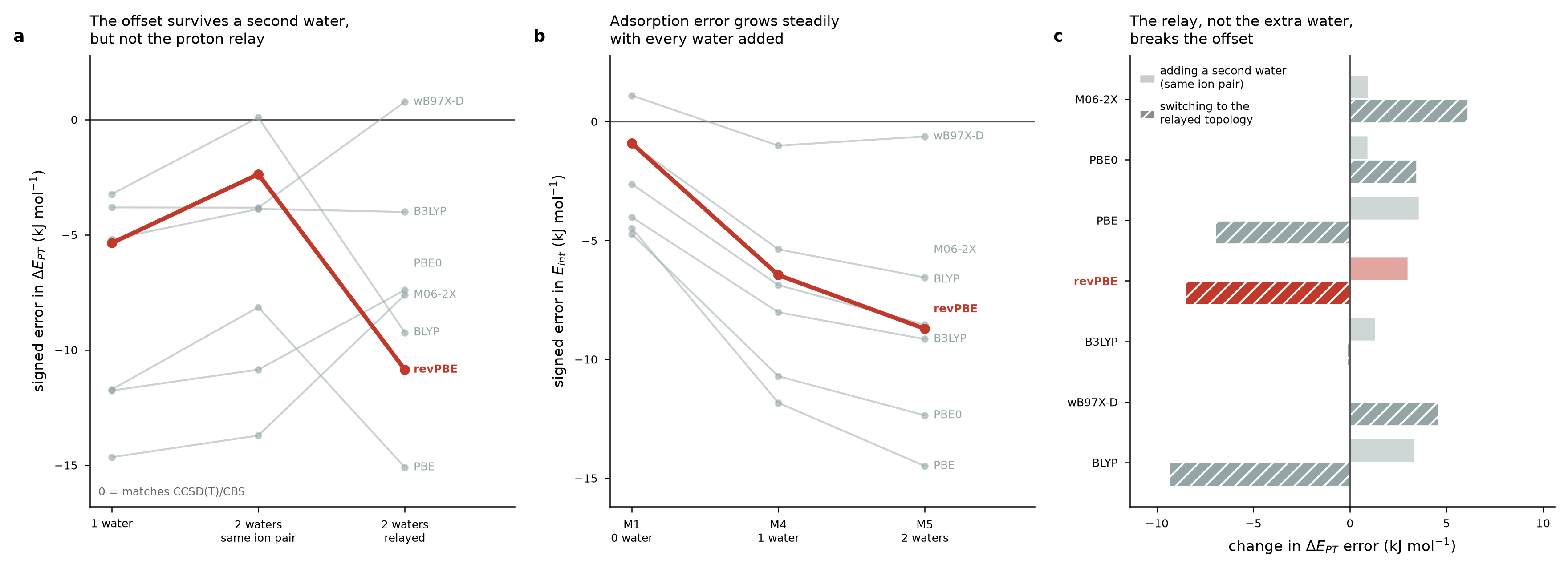 Original study output
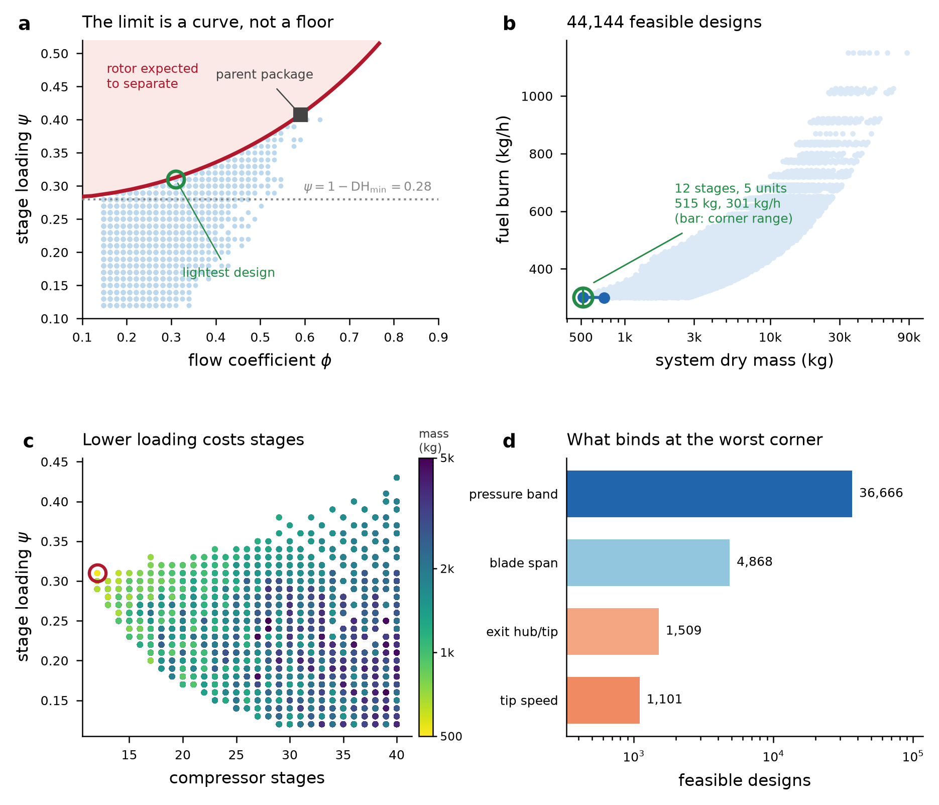 Original study output
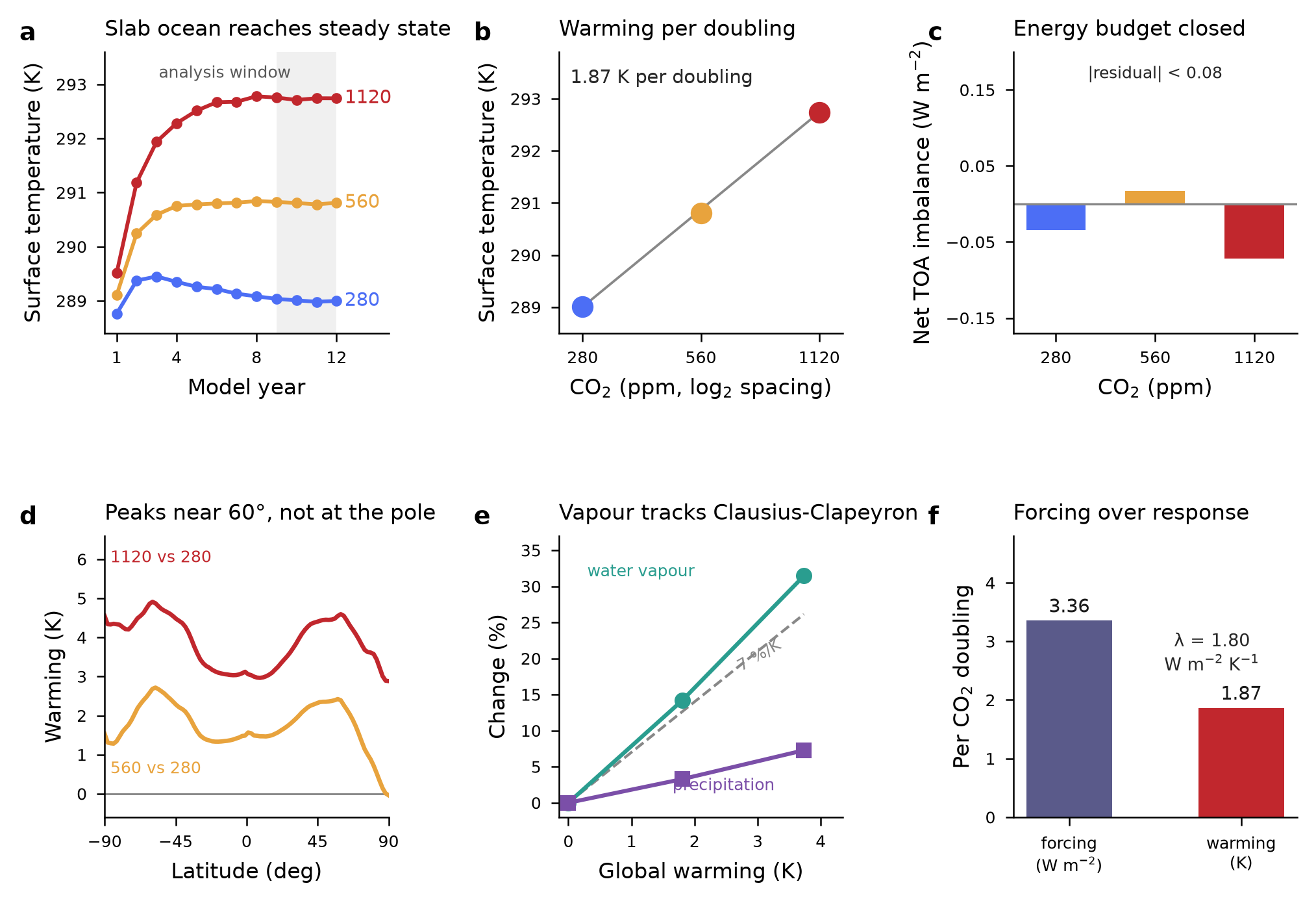 Original study output
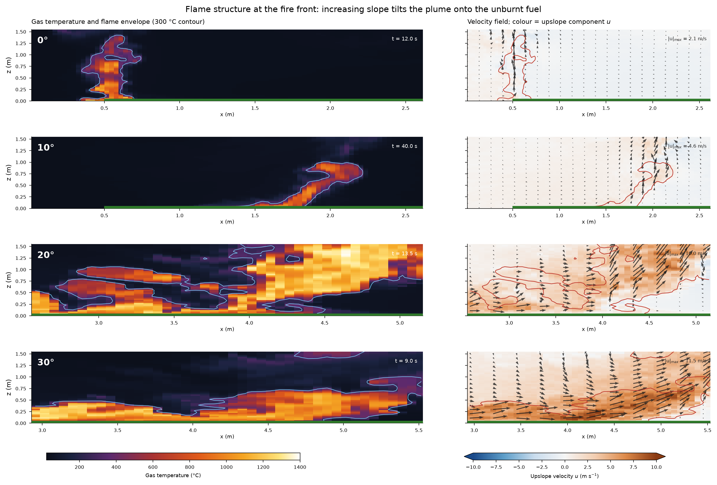 Original study output
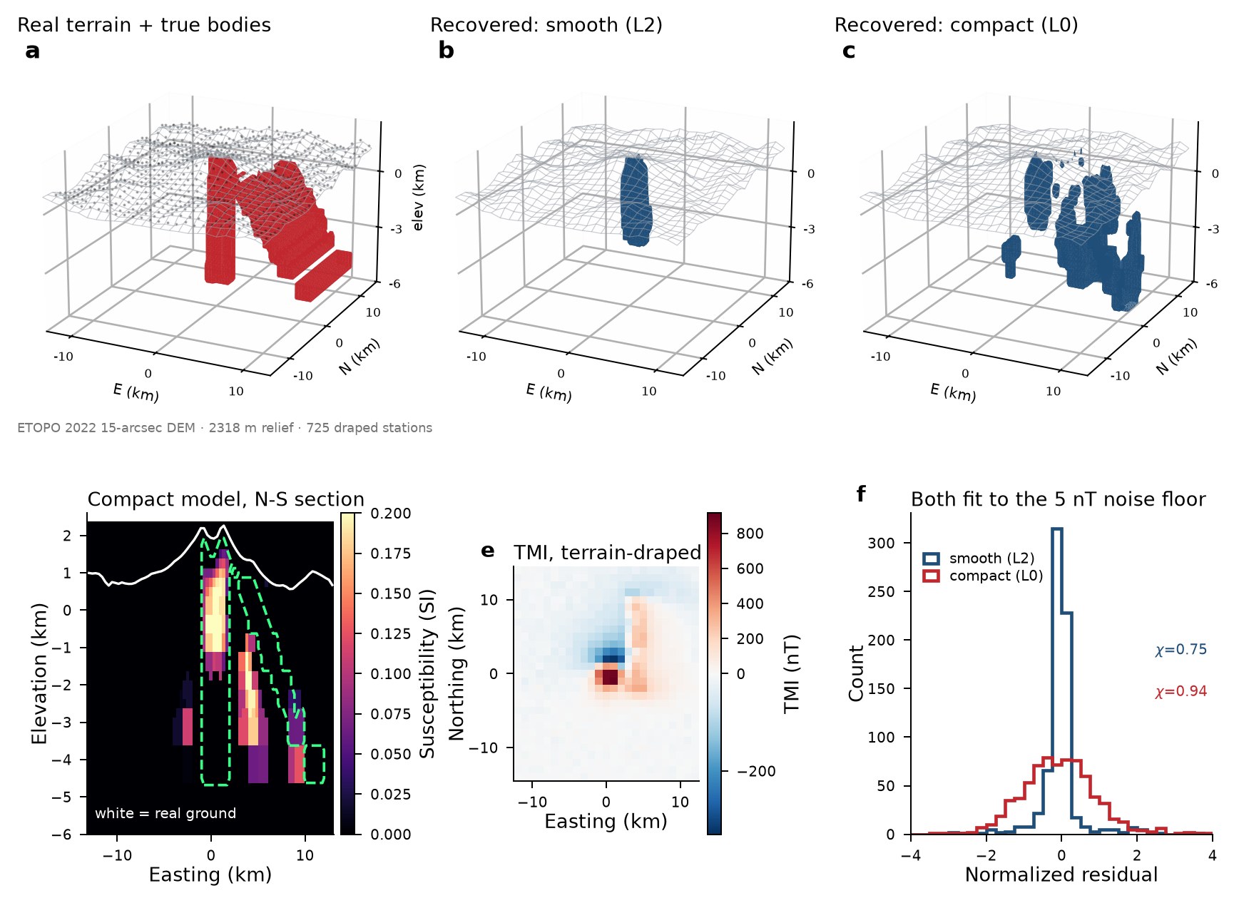 Original study output
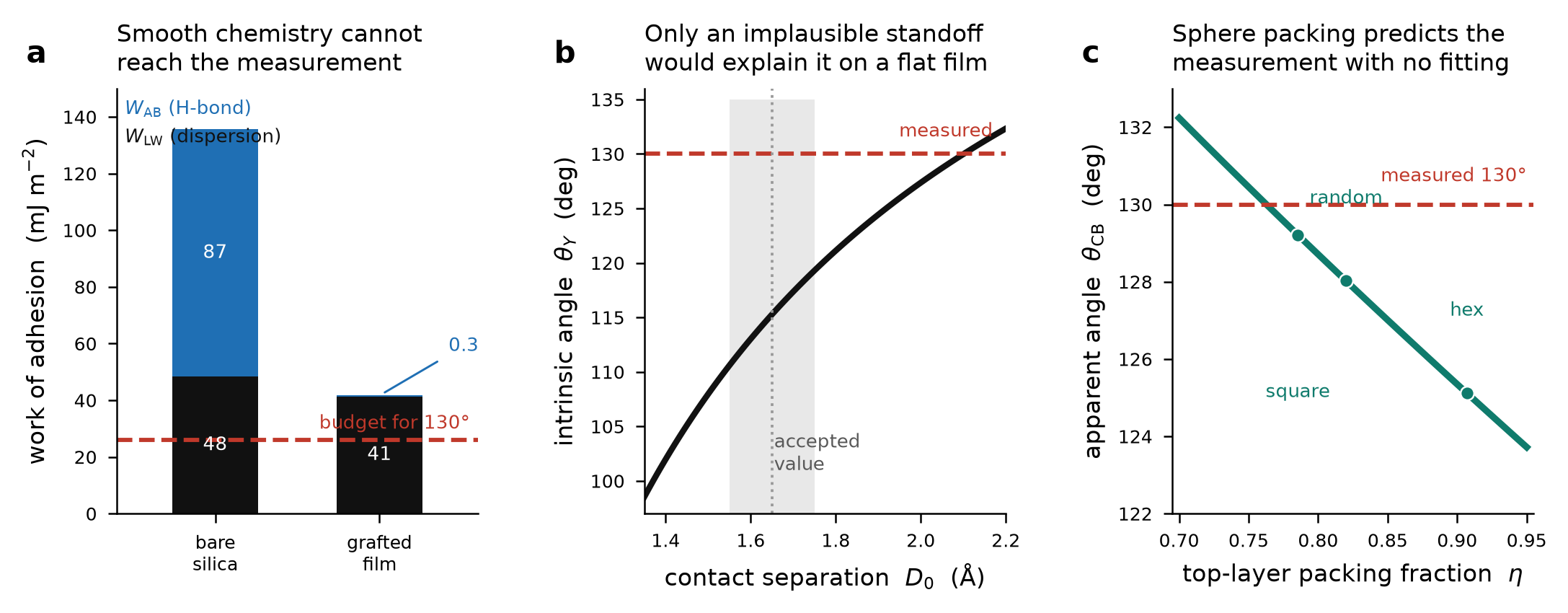 Original study output
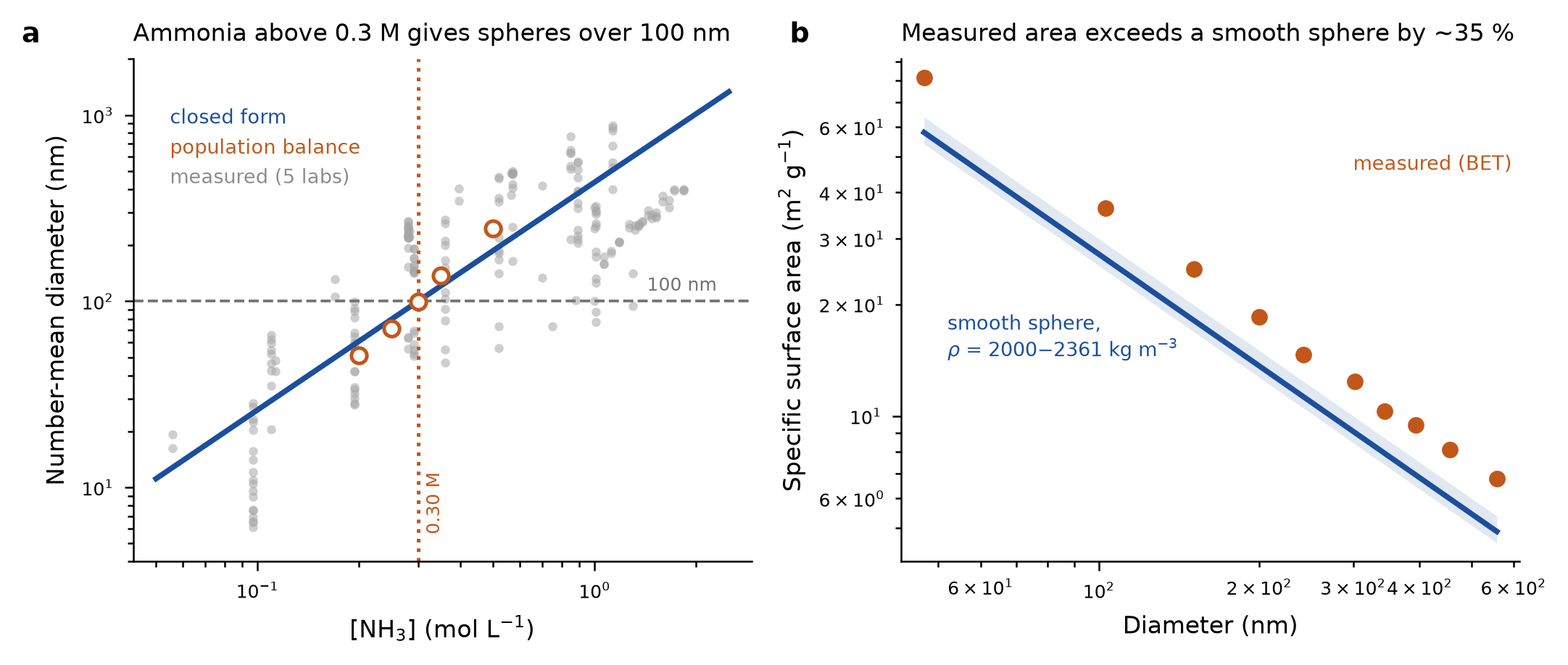 Original study output
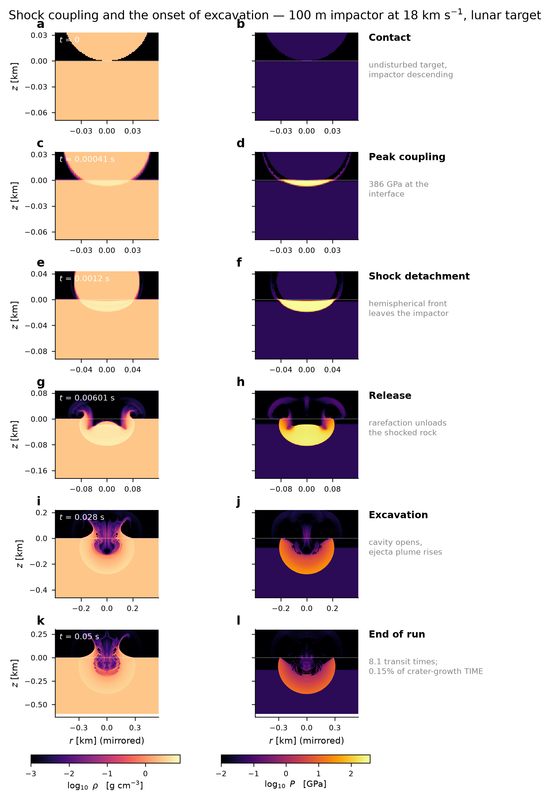 Original study output
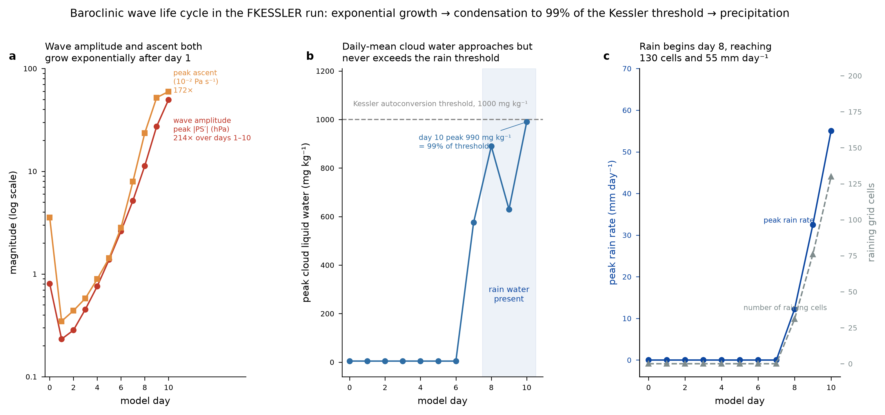 Original study output
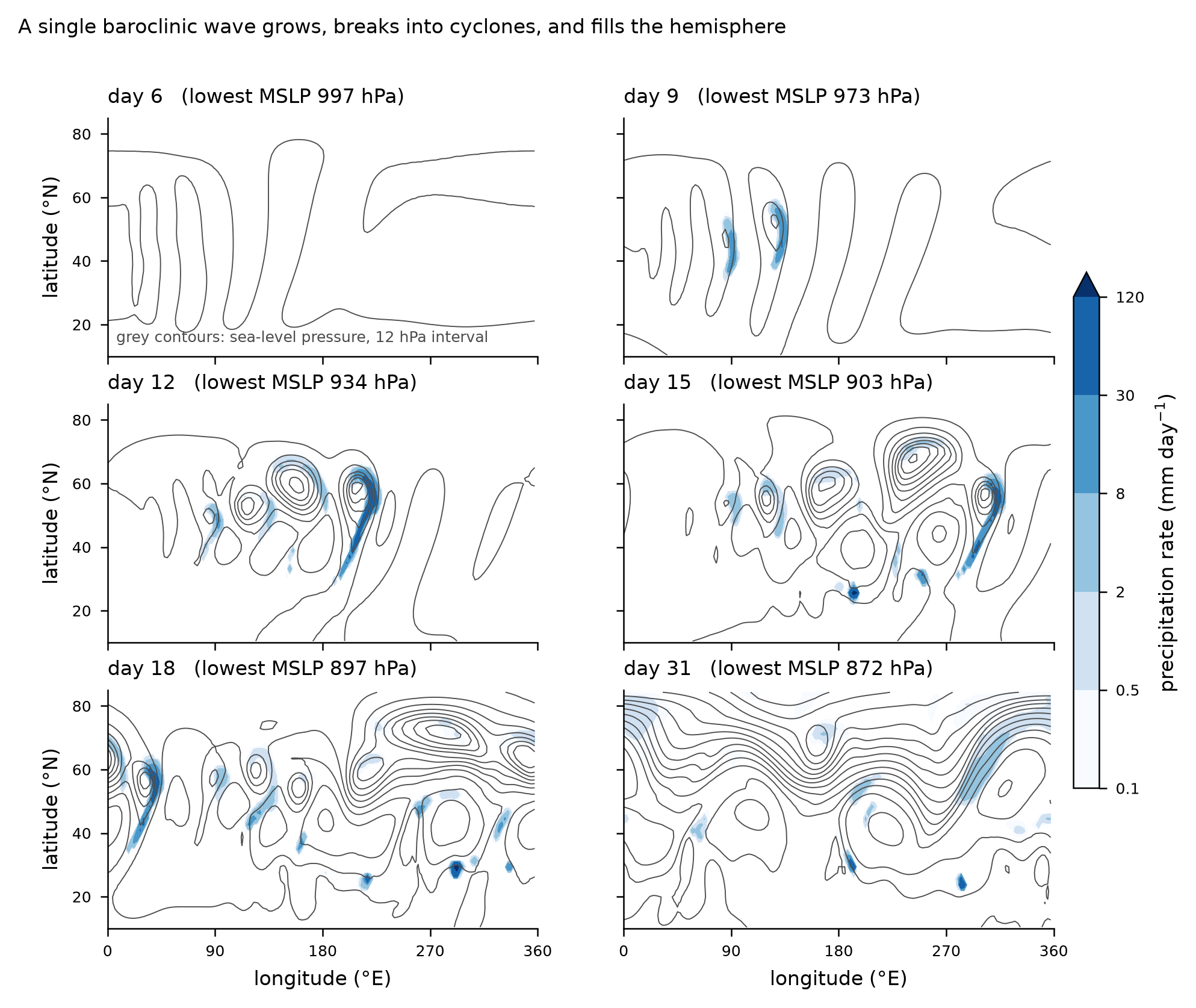 Original study output
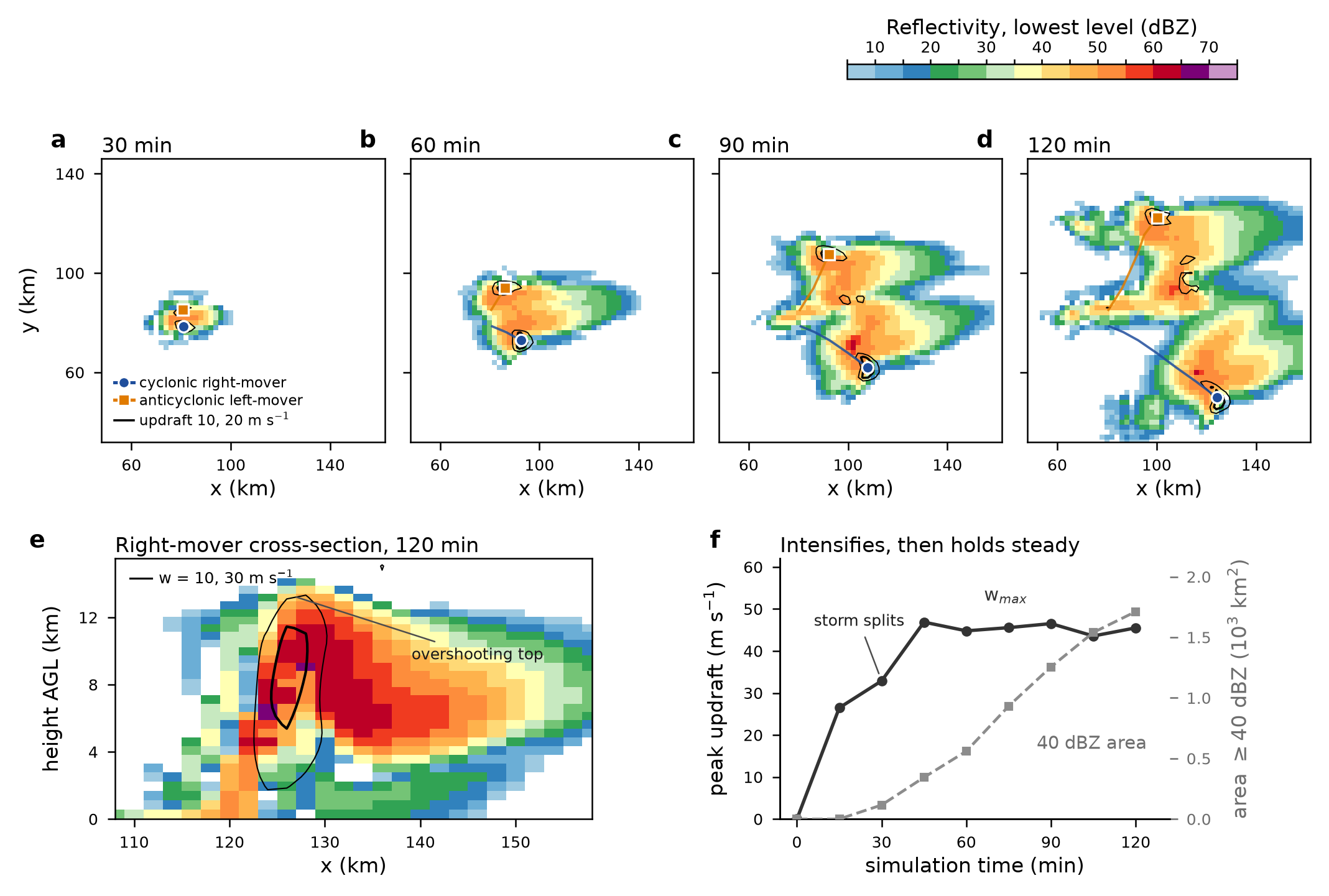 Original study output
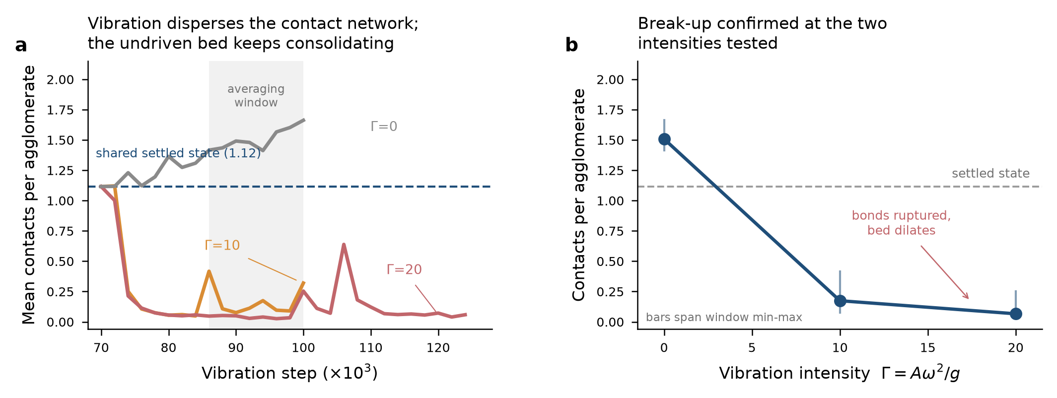 Original study output
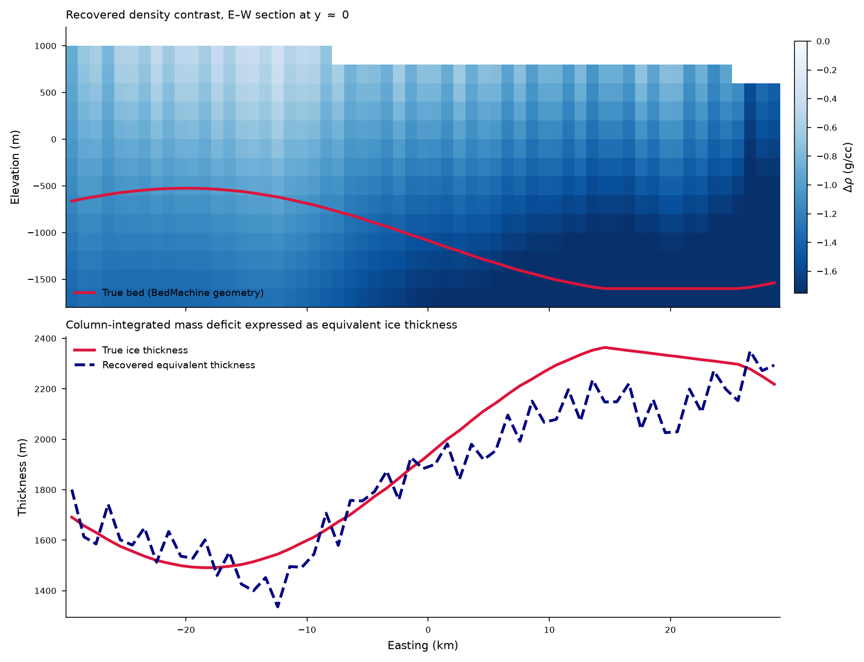 Original study output
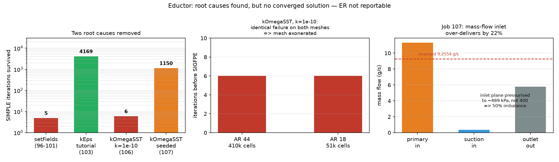 Original study output